Chapter 10
Routing in Linux
10.1.1 Assumed Knowledge
10.1.2 Linux and Network Setup
10.2 Routers
10.2.1 Routers and Hosts
10.2.2 Enabling Routing
10.2.3 Editing the Routing Table
10.3 Networking Setup Example
10.3.1 Prerequisites
10.3.2 Setting IP Addresses
10.3.3 Enable Forwarding
10.3.4 Add Routes
10.3.5 Testing the Internet
Although Ethernet is a common technology for layer 2 networks, in particular LANs, there are in fact many different technologies for layer 2 networks, including for WANs: Ethernet, Asymmetric Digital Subscriber Line (ADSL), Synchronous Digital Hierarchy (SDH), Wireless LAN, Bluetooth, Token Ring, Frame Relay, Asynchronous Transfer Mode (ATM), . Therefore to allow a user to communicate with any other user, independent of the LAN/WAN technology, layer 3 networking is used. Today, the Internet Protocol (IP) is the most commonly used layer 3 network technology. At layer 3, routers are used to connect LANs and WANs together, e.g. connect an Ethernet LAN to a SDH WAN; connect two Ethernet LANs together; connect a ATM WAN to a Frame Relay WAN; and so on.
This chapter shows you how to create a layer 3 network. That is, you will use setup a router so that hosts in separate layer 2 networks can communicate. As Linux is being used, the router will simply be a normal computer with multiple NICs: no special hardware is needed for the router. As only a small network is deployed, we only use static routing. Dynamic routing protocols, such as Open Shortest Path First (OSPF) and Routing Information Protocol (RIP), are not configured in this chapter.
10.1 Prerequisites
10.1.1 Assumed Knowledge
This chapter assumes you have knowledge of:
- The Internet, IP and routing, including: the difference between routers and hosts; reading and creating routing tables; and IP forwarding rules.
- IPv4 addressing, including subnet masks and broadcast addresses.
Basic Linux command line skills, as covered in Chapter 4, are assumed. You will need to be able to:
- View and edit files, e.g. with cat or nano.
- Perform operations on directories and files, including ls, cd, cp.
- Apply networking tools as covered in Chapter 9.
10.1.2 Linux and Network Setup
To complete the practical tasks in this chapter you need multiple Linux computers. You are recommended to use virtnet (Chapter 3), as it allows for quick deployment of the computers. Although virtnet actually configures routing for you, we will show how to manually configure routing within virtnet nodes.
The recommended virtnet topology is:
Other topologies with at least two subnets could also be used.
10.2 Routers
An internet is a collection of many different computer networks (LANs and WANs) connected together. Routers are devices that connect these individual networks together.
A router has two main roles:
- Routing. This is the process of discovering suitable routes throughout an internet. This is normally done automatically (using a routing protocol) but routes can be created manually (we will see how in this lab). Think of a route as the path through the internet.
- Forwarding. This is the process undertaken when a router receives an IP datagram. The router looks at the destination IP address in the datagram, and from the routers routing table, determines what is the next router (or host) to send the datagram to in order to reach the final destination. Then the router sends the datagram.
10.2.1 Routers and Hosts
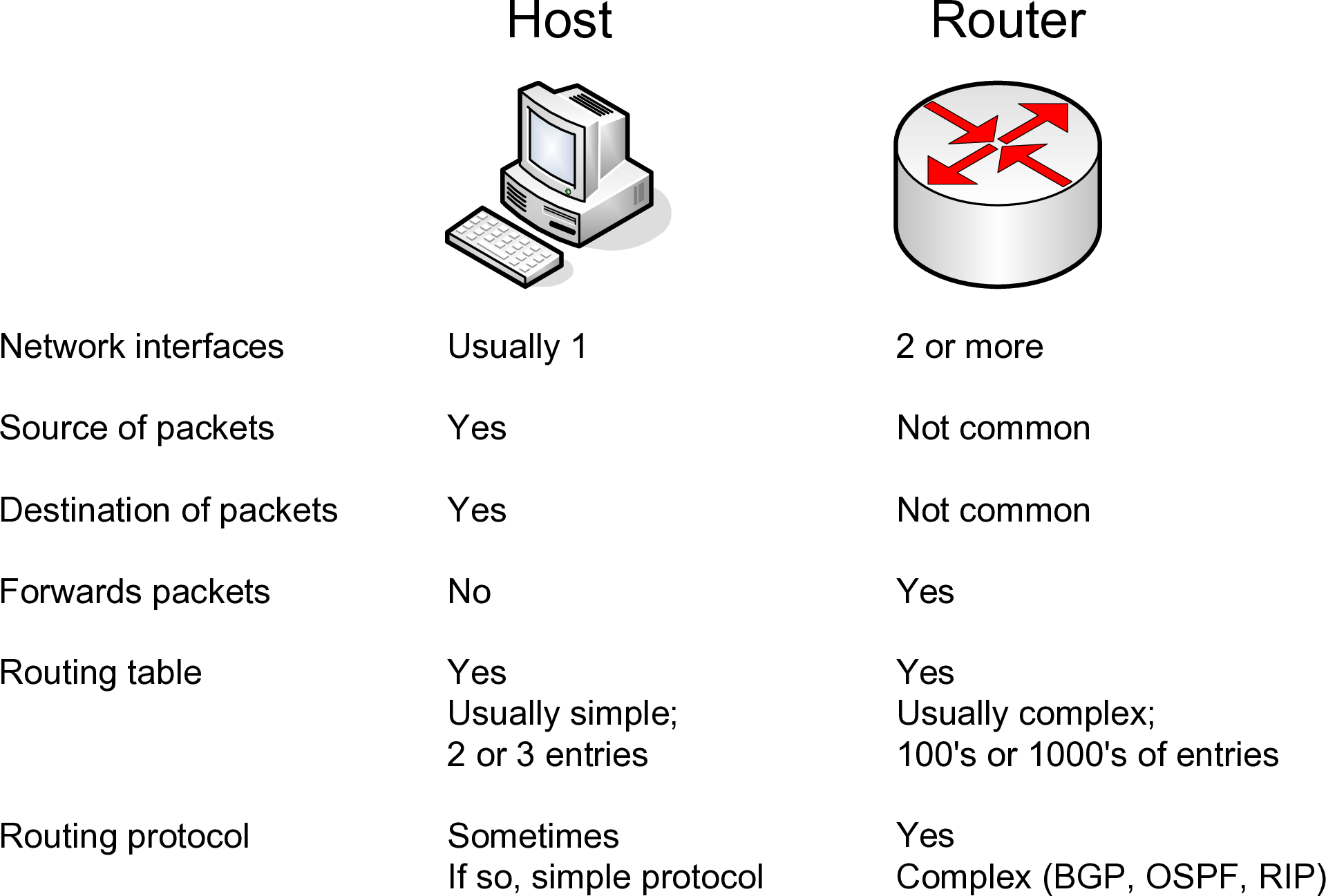
What is the difference between a host (e.g. your PC) and router?
- When a host receives an IP datagram destined to itself, then the host will process the datagram by sending it to the relevant application (e.g. web browser). If the host receives an IP datagram destined to an IP address other than itself, the datagram will be dropped.
- In the case of receiving an IP datagram destined to itself, the router will do the same as the host. But when a router receives an IP datagram destined to another IP address, the router will look up its routing tables and forward the datagram to another computer (host or router).
A simple example: an IP datagram with destination address 200.0.0.3 is received at a computer with IP address 192.168.1.1. If the computer is a host, the datagram will be dropped (discarded). If the computer is a router, the datagram will be forwarded to the next router in the path. In summary, a router will forward datagrams; a host will not forward datagrams.
A router knows where to forward an IP datagram based on its routing tables. The routing tables, in their simplest form, say: if a datagram is destined to network X, then send it to the next router Y. In fact, both a router and a host have a routing table. The table in the router may be quite complex (with many rows or entries), whereas in a host it is usually just a single entry specifying the default router (or as we have seen, default gateway—gateway and router are the same in this context).
For a router, the routing tables are created using routing protocols. The routing protocols are implemented as software applications. During network operation, the routers in the internet communicate with each other to discover the best paths through the internet. Alternatively, the routing tables can be created manually by adding entries to the routing table. In this chapter as the aim is to learn about routing in only small networks, we will create all entries manually. Dynamic routing protocols such as OSPF and RIP will not be used.
Figure 10.1 summarises the differences between routers and hosts.
10.2.2 Enabling Routing
There is only a small difference in functionality between a router and host (however, for a real network, there may be big differences in implementation and performance: for example, a commercial router often has hardware and an operating system dedicated to the task of routing, whereas a PC uses general purpose hardware and operating systems). In practice it is easy to make a host become a router. That is, most PCs can be configured as a router if:
- They have two or more network interfaces
- The operating system is configured to enable forwarding
On Ubuntu Linux, by default, forwarding is off . The status of forwarding is maintained by the Linux kernel and is given in the file /proc/sys/net/ipv4/ip_forward. The file simply contains a 0 or 1: a 0 indicates off while a 1 indicates on:
There are several ways to tell the Linux kernel to enable forwarding:
- Edit the file /proc/sys/net/ipv4/ip_forward, replacing 0 with 1. This change is not persistent across reboots. That is, rebooting your computer will refer back to the default.
- Use the command sysctl to set the ip_forward parameter:
$ sysctl net.ipv4.ip_forward=1The command sysctl will edit the file /proc/sys/net/ipv4/ip_forward on your behalf. Again, the change is not persistent across reboots.
- Edit the file /etc/sysctl.conf, ensuring net.ipv4.ip_forward is set to 1 and uncommented (remove the hash from the start of the line). This change only takes effect when the system reboots (i.e. the change is persistent) or by reloading the configuration file with the command sysctl -p.
You can also use the above commands to disable forwarding: just set the value to 0. Note that all the approaches require administrator privileges, so commands will need to be preceeded with sudo. You are recommended to use approach 2 from above, and if you also need persistence across reboots, also use approach 3.
$ sudo sysctl net.ipv4.ip_forward=1
Note: /proc and Linux Kernel Configuration
The /proc directory in Linux is actually a special filesystem that keeps track of processes and
Linux system information. While it appears as files and directories, it is actually just a way in
which the Linux kernel internal information is exposed to the user. You can read more about
/proc in the Linux Filesystem Hierarchy book.
Various kernel networking parameters can be viewed within the /proc/sys/net directory, including parameters for IP, TCP, UDP and ICMP. Most of the files simply contain the parameter value. For example, the TCP congestion control algorithm in use can be seen:
$ cat /proc/sys/net/ipv4/tcp_congestion_control
cubic
While you can also change the parameters by editing the files, it is often better to use the sysctl command to edit the files for you. In that way, basic checking of the parameter values will be performed to avoid errors. sysctl controls the values within /proc/sys and uses dots (.) to separate the groupings:
$ sysctl net.ipv4.tcp_congestion_control
net.ipv4.tcp_congestion_control = cubic
Setting values normally needs sudo. Here is an example, but don’t do this, or at least change back to cubic afterwards:
$ sudo sysctl net.ipv4.tcp_congestion_control=reno
net.ipv4.tcp_congestion_control = reno
$ sudo sysctl net.ipv4.tcp_congestion_control=cubic
net.ipv4.tcp_congestion_control = cubic
To see all parameters, use sysctl -a. Descriptions of all parameter can be found within the Linux kernel documentation. There are general parameters (look in the .txt files) and networking parameters (look in the *-sysctl.txt files). The most relevant for this book is ip-sysctl.txt which describes ip_forward, tcp_congestion_control and many other TCP/IP parameters.
10.2.3 Editing the Routing Table
In large internets, routing protocols are used to automatically create the routing tables. In small internets, we can manually configure the routes. To do this, we must add routes to the routing tables.
In Ubuntu, the route command shows the current routing table. Usually, for a host there will be only a few entries, such as for node1. This routing table is explained in Section 9.8.
network@node1:~$ route -n
Kernel IP routing table
Destination     Gateway         Genmask         Flags Metric Ref    Use Iface
0.0.0.0         10.0.2.2        0.0.0.0         UG    0      0        0 eth0
10.0.2.0        0.0.0.0         255.255.255.0   U     0      0        0 eth0
192.168.0.0     192.168.1.1     255.255.0.0     UG    0      0        0 eth1
192.168.1.0     0.0.0.0         255.255.255.0   U     0      0        0 eth1
For routers, entries will be needed to specify the routes to different networks.
In order to add a route, you can use the add option:
$ route add -net NETWORKADDRESS netmask SUBNETMASK gw NEXTROUTER dev INTERFACE
where:
- NETWORKADDRESS is the IP address representing the destination network, e.g. network 192.168.1.0
- SUBNETMASK is the subnet mask for the destination network, e.g. 255.255.255.0
- NEXTROUTER is the IP address next router in the path to the destination network, e.g. 192.168.3.1
- INTERFACE is the network interface to send the datagram on, e.g. eth2
Similarly, you can delete an entry with:
$ route del -net NETWORKADDRESS netmask SUBNETMASK
10.3 Networking Setup Example
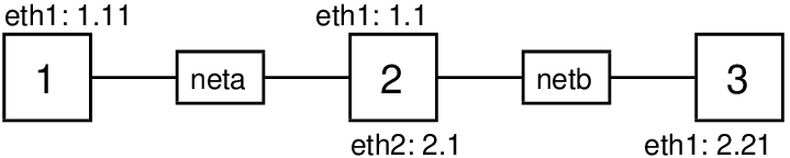
To demonstrate forwarding, routing and IP address configuration we will setup a simple internet consisting of three nodes as shown in Figure 10.2.
10.3.1 Prerequisites
virtnet
If you are using virtnet, then we are going to start with topology 5. This actually already has the desired network setup for us, so to demonstrate the steps we will first disable the current settings on each node.
Firstly, log in to each of the nodes using VirtualBox. As we are going to turn off all interfaces you must not use PuTTY or SSH to login; you must use the VirtualBox interface.
Then on each node you must turn off all interfaces, as shown below (which also checks that the interfaces are off and routing tables entry using).
On node1, turn off eth0 and eth1:
network@node1:~$ sudo ifconfig eth0 down
network@node1:~$ sudo ifconfig eth1 down
network@node1:~$ ifconfig
lo        Link encap:Local Loopback
            inet addr:127.0.0.1  Mask:255.0.0.0
            inet6 addr: ::1/128 Scope:Host
            UP LOOPBACK RUNNING  MTU:65536  Metric:1
            RX packets:0 errors:0 dropped:0 overruns:0 frame:0
            TX packets:0 errors:0 dropped:0 overruns:0 carrier:0
            collisions:0 txqueuelen:1
            RX bytes:0 (0.0 B)  TX bytes:0 (0.0 B)
network@node1:~$ route -n
Kernel IP routing table
Destination     Gateway         Genmask         Flags Metric Ref    Use Iface
On node2, turn off eth0, eth1 and eth2:
network@node2:~$ sudo ifconfig eth0 down
network@node2:~$ sudo ifconfig eth1 down
network@node2:~$ sudo ifconfig eth2 down
network@node2:~$ ifconfig
lo        Link encap:Local Loopback
            inet addr:127.0.0.1  Mask:255.0.0.0
            inet6 addr: ::1/128 Scope:Host
            UP LOOPBACK RUNNING  MTU:65536  Metric:1
            RX packets:0 errors:0 dropped:0 overruns:0 frame:0
            TX packets:0 errors:0 dropped:0 overruns:0 carrier:0
            collisions:0 txqueuelen:1


            RX bytes:0 (0.0 B)  TX bytes:0 (0.0 B)
network@node2:~$ route -n
Kernel IP routing table
Destination     Gateway         Genmask         Flags Metric Ref    Use Iface
On node3, turn off eth0 and eth1. The commands and output are not shown here, as they are similar to node1.
Using a real network
If you are using your own computers (within virtualisation software or real computers) then you need to setup the connections between those computers. That is, if you are using real computers, the router computer requires two NICs with a LAN cable going to each of the other two computers. If you are using virtualisation software (other than virtnet), then you will need to configure that software so that the three virtual machines are configured in the desired topology in Figure 10.2.
10.3.2 Setting IP Addresses
We will first set the IP addresses on each of the nodes.
On node1:
network@node1:~$ sudo ifconfig eth1 172.16.5.10/24 up
network@node1:~$ ifconfig eth1
eth1      Link encap:Ethernet  HWaddr 08:00:27:51:52:b4
            inet addr:172.16.5.10  Bcast:172.16.5.255  Mask:255.255.255.0
            inet6 addr: fe80::a00:27ff:fe51:52b4/64 Scope:Link
            UP BROADCAST RUNNING MULTICAST  MTU:1500  Metric:1
            RX packets:0 errors:0 dropped:0 overruns:0 frame:0
            TX packets:15 errors:0 dropped:0 overruns:0 carrier:0
            collisions:0 txqueuelen:1000
            RX bytes:0 (0.0 KB)  TX bytes:1226 (1.2 KB)
On node2:
network@node2:~$ sudo ifconfig eth1 172.16.5.20/24 up
network@node2:~$ sudo ifconfig eth2 172.16.6.30/24 up
On node3:
network@node3:~$ sudo ifconfig eth1 172.16.6.40/24 up
10.3.3 Enable Forwarding
On node2, our router, enable forwarding:
network@node2:~$ sudo sysctl net.ipv4.ip\_forward=1
net.ipv4.ip\_forward = 1
10.3.4 Add Routes
If you check the routing tables currently on the nodes you will see that by setting an IP address a routing entry for the local network is automatically added. For example, on node1:
network@node1:~$ route -n
Kernel IP routing table
Destination     Gateway   Genmask         Flags Metric Ref    Use Iface
172.16.5.0      0.0.0.0   255.255.255.0   U     0      0      0   eth1
And on node2:
network@node2:~$ route -n
Kernel IP routing table
Destination     Gateway   Genmask         Flags Metric Ref    Use Iface
172.16.5.0      0.0.0.0   255.255.255.0   U     0      0      0   eth1
172.16.6.0      0.0.0.0   255.255.255.0   U     0      0      0   eth2
Therefore we only need to add routes for the hosts (node1 and node3) to the other subnets. The router (node2) does not need additional routes, since it can reach both subnets directly.
On node1:
network@node1:~$ route add -net 172.16.6.0 netmask 255.255.255.0 gw 172.16.5.20 dev eth1
network@node1:~$ route -n
Kernel IP routing table
Destination     Gateway     Genmask         Flags Metric Ref    Use Iface
172.16.5.0      0.0.0.0     255.255.255.0   U     0      0      0   eth1
172.16.6.0      172.16.5.20 255.255.255.0   UG    0      0      0   eth1
We can do the same on node3. However there is another approach to the routing table design. For node1, we added an entry to a specific subnet (172.16.6.0). Alternatively, we could add a default route that matches all other subnets. In this simple network, both approaches achieve the desired outcome. For node3 the following shows adding a default route.
network@node3:~$ route add default gw 172.16.6.30 dev eth1
network@node3:~$ route -n
Kernel IP routing table
Destination     Gateway     Genmask         Flags Metric Ref    Use Iface
0.0.0.0         172.16.6.30 255.255.255.0   UG    0      0      0   eth1
172.16.6.0      0.0.0.0     255.255.255.0   U     0      0      0   eth1
10.3.5 Testing the Internet
First let’s use ping to test. On node1, we will attempt to communicate with the router (both interfaces) and then node3.
network@node1:~$ ping -c 3 172.16.5.20
PING 172.16.5.20 (172.16.5.20) 56(84) bytes of data.
64 bytes from 172.16.5.20: icmp_seq=1 ttl=64 time=2.09 ms
64 bytes from 172.16.5.20: icmp_seq=2 ttl=64 time=2.39 ms
64 bytes from 172.16.5.20: icmp_seq=3 ttl=64 time=2.11 ms

--- 172.16.5.20 ping statistics ---
3 packets transmitted, 3 received, 0% packet loss, time 2005ms
rtt min/avg/max/mdev = 2.090/2.201/2.399/0.140 ms
network@node1:~$ ping -c 3 172.16.6.30
PING 172.16.6.30 (172.16.6.30) 56(84) bytes of data.
64 bytes from 172.16.6.30: icmp_seq=1 ttl=64 time=1.92 ms
64 bytes from 172.16.6.30: icmp_seq=2 ttl=64 time=2.13 ms
64 bytes from 172.16.6.30: icmp_seq=3 ttl=64 time=1.92 ms

--- 172.16.6.30 ping statistics ---
3 packets transmitted, 3 received, 0% packet loss, time 2003ms
rtt min/avg/max/mdev = 1.929/1.998/2.137/0.104 ms
network@node1:~$ ping -c 3 172.16.6.40
PING 172.16.6.40 (172.16.6.40) 56(84) bytes of data.
64 bytes from 172.16.6.40: icmp_seq=1 ttl=63 time=3.67 ms
64 bytes from 172.16.6.40: icmp_seq=2 ttl=63 time=1.84 ms
64 bytes from 172.16.6.40: icmp_seq=3 ttl=63 time=3.97 ms

--- 172.16.6.40 ping statistics ---
3 packets transmitted, 3 received, 0% packet loss, time 2003ms
rtt min/avg/max/mdev = 1.844/3.162/3.973/0.942 ms
This demonstrates that our internet is working, with node1 pinging node3, via node2 (note the Time To Live (TTL) is 63 in the final ping).
You could test with other applications, such as ssh and wget, as well if desired.
Note that the IP addresses, forwarding configuration on the router, and routing table entries are not persistent. They will be lost upon reboot. To make them persistent consider editing /etc/network/interfaces (Section 9.11.4) and /etc/sysctl.conf (Section 9.11.7). For examples of the interfaces file that sets IP addresses and routes, look inside the files on the virtnet nodes.
If you want to revert back to the previous configuration (in the case of virtnet topology 5), simply reboot the machines.