File: Steve/Courses/2014/s2/its332/layer3.tex, r3455
Although Ethernet is a common technology for layer 2 networks, in particular LANs, there are in fact many different technologies for layer 2 networks, including for WANs: Ethernet, ADSL, SDH, Wireless LAN, Bluetooth, Token Ring, Frame Relay, ATM, …. Therefore to allow a user to communicate with any other user, indepdenent of the LAN/WAN technology, layer 3 networking is used. Today, the Internet Protocol (IP) is the most commonly used layer 3 network technology. At layer 3, routers are used to connect LANs and WANs together, e.g. connect an Ethernet LAN to a SDH WAN; connect two Ethernet LANs together; connect a ATM WAN to a Frame Relay WAN; and so on.
In this lab you will create layer 3 network. That is, you will connect different LANs/WANs together using routers. The main tasks will be configuring the hosts and routers to use the appropriate addresses and routing tables.
An internet is a collection of many different computer networks (LANs and WANs) connected together. Routers are devices that connect these individual networks together.
A router has two main roles:
What is the difference between a host (e.g. your PC) and router?
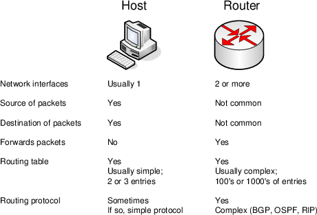
A simple example: an IP datagram with destination address 200.0.0.3 is received at a computer with IP address 192.168.1.1. If the computer is a host, the datagram will be dropped (discarded). If the computer is a router, the datagram will be forwarded to the next router in the path. In summary, a router will forward datagrams; a host will not forward datagrams.
A router knows where to forward an IP datagram based on its routing tables. The routing tables, in their simplest form, say: if a datagram is destined to network X, then send it to the next router Y. In fact, both a router and a host have a routing table. The table in the router may be quite complex (with many rows or entries), whereas in a host it is usually just a single entry specifying the default router (or as we have seen, default gateway—gateway and router are the same in this context).
For a router, the routing tables are created using routing protocols. The routing protocols are implemented as software applications. During network operation, the routers in the internet communicate with each other to discover the best paths through the internet. Alternatively, the routing tables can be created manually by adding entries to the routing table.
Figure 7.1 summarises the differences between routers and hosts.
There is only a small difference in functionality between a router and host (however, for a real network, there may be big differences in implementation and performance: for example, a commercial router often has hardware and an operating system dedicated to the task of routing, whereas a PC uses general purpose hardware and operating systems). In practice it is easy to make a host become a router. That is, most PCs can be configured as a router if:
On Ubuntu Linux, by default forwarding is off. The status of forwarding is maintained by the Linux kernel and is given in the following file—a 0 indicates off while a 1 indicates on:
To change the value you can edit the file (if you have permissions) or use sysctl as follows:
Similarly you can use sysctl to turn off forwarding.
In large internets, routing protocols are used to automatically create the routing tables. In small internets, we can manually configure the routes. To do this, we must add routes to the routing tables.
In Ubuntu, the route command shows the current routing table. Usually, for a host there will be a single entry like:
This says, for all IP datagrams that are destined outside of this network, send them to the default router (192.168.1.1).
And for a simple, two interface router, there may be more entries to specify the routes to different networks. In order to add a route, you can use the add option:
where:
Similarly, you can delete an entry with:
On the following tasks you should record the design of the network, record relevant results from the tests, and demonstrate your network to the instructor.
Task 7.1. Create and test an internet that has two subnets: one subnet has two hosts connected via an Ethernet switch; the other subnet has a single host.
Task 7.2. Create and test an internet that has three subnets: two subnets have a single host; the third subnet simply connects two routers together.
Task 7.3. Create and test an internet that joins your three subnets from Task 7.2 with another groups three subnets.