Figure 6.1: Layer 2 Peer-to-peer Network
File: Steve/Courses/2014/s2/its332/layer2.tex, r3455
The simplest computer network that can be created connects two computers directly together via cable (that is, a peer-to-peer network). Creating such a network will introduce you to the methods for physically connecting computers (including cable types), and configuring interfaces for computers to be on the same network.
A more useful, and much more common network is a switched Ethernet LAN, where multiple computers are connected to a switch. You will setup your own LAN, configuring all computers on the network.
This lab concentrates on Layer 2 network technologies, in particular Ethernet. The next lab will look at Layer 3 networks, that is, joining two or more Layer 2 networks together using IP routers.
The simplest network is one that connects two computers together, usually directly via a cable. This requires both computers to use the same Layer 2 network technology, with common options being Ethernet, a serial link, Wireless LAN or Bluetooth.
Connecting two computers with a cable (e.g. Ethernet or serial link) is mainly useful for simple demonstrations (like this lab), simple, high speed file transfer and for troubleshooting. As an example of troubleshooting, if two computers are connected together and can communicate with each other then that usually means the LAN cards and network software work correctly. Therefore there are other problems if one of the computers cannot successfully communicate when connected to a switched LAN or internet.
Connecting two computers via wireless technologies (e.g. Wireless LAN, Bluetooth, infrared) is commony used for temporary and/or spontaneous sharing of data.
As we will see, connecting two computers (and configuring them to communicate with each other) is quite simple. However, the applications are rather limited as you cannot communicate with anyone else.
Note 1. (Ethernet, Fast Ethernet, Gigabit Ethernet) Although there are different variants of IEEE 802.3, including Ethernet (10Mb/s), Fast Ethernet (100Mb/s) and Gigabit Ethernet (1Gb/s), we will often use the word Ethernet in the general sense, that refers to either of the variants. In fact, the computers in the lab are configured with Fast Ethernet LAN cards (although can operate at 1Gb/s Ethernet).
Note 2. (Other Types of Peer-To-Peer Networks) You may hear of Peer-to-Peer Networks or P2P file sharing to describe many applications and services in use on the Internet today. Although they are based on similar principles (all nodes are equal, no central point of control), the technologies and protocols used are not the same. In this lab we are only dealing with the method of connecting two computer together: any type of application can run on the two computers (Email, Web server, P2P File sharing), although may have limited use with only two people involved.
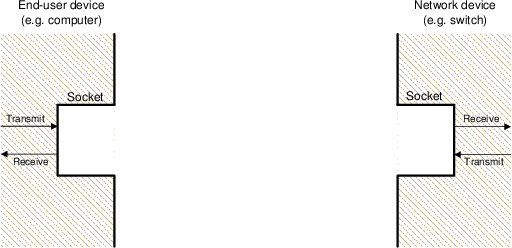
Ethernet, in particular Fast Ethernet, is a full-duplex communications protocol. That is, device A can transmit to device B at the same time as device A is receiving from device B. This is performed by having a set of separate wires for transmit and receive. So in an Ethernet cable there are many individual wires, one set that are used for transmitting and one set for receiving.
In Ethernet networks, there are two types of devices:
To be able to transmit from one device and receive at the other device, the ordering of the transmit and receive sets of wires in the cable must be correct. The socket into which you plug the Ethernet cable must be wired correctly as well. The wiring in sockets of end-user devices is different than that in network devices. A simple way to understand this is as follows.
Lets assume the transmit wires in the socket of an end-user device (e.g. computer LAN card) are at the top, and receive wires at the bottom, as illustrated in Figure 6.2. And the opposite applies for the socket of a network device (e.g. switch).
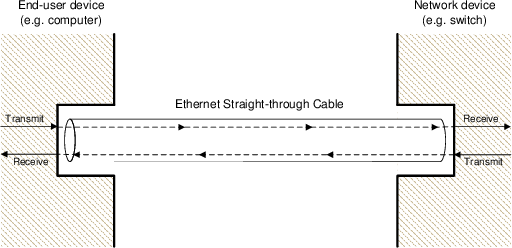
Of course, the transmit wires in the socket of one device must connect to the receive wires in the socket of the other device. Hence to connect an end-user device to a network device, the wires in the Ethernet cable must go straight-through to the other side, as shown in Figure 6.3.
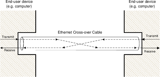
However, if we now want to connect an end-user device to another end-user device (such as in the peer-to-peer network, where we connect one computer directly to another), then the wires in the Ethernet cable must cross-over, as shown in Figure 6.4.
In summary, there are two different types of Ethernet cables for connecting devices:
How do you tell the difference between a straight-through and cross-over cable? From the colours of the individual wires that you see at the end points of the cables. For a straight-through cable, if you look at the end-points from the same viewpoint, the colours will be in the same order. For a cross-over cable, the colours will be in a different order.
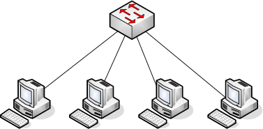
Connecting only two computers has very limited use. Usually a user or organisation has more than two computers to connect together. There are different topologies that can be used to connect computers together, although today the most common is a star-based topology, where the centre of the star is a Layer 2 Switch. Hence, referred to as a switched network.
In a switched network, all end-user devices have individual cables to the central switch. In most cases, the connection to the switch is full-duplex. To transmit from one end-user device to another, the transmission goes via the switch. Of course, often users want to communicate with other users not on the same switched network. Hence the switch can also be connected to another switch to connect to another switched network, or to a router, to connect to any network.
On the following tasks you should record the design of the network, record relevant results from the tests, and demonstrate your network to the instructor.