Impact of Bandwidth Delay Product on TCP Throughput
To understand how TCP works its often useful to run experiments to see what parameters in the network and protocols impact on TCP performance (in particular, throughput). The problem is that in real systems the functionality offered by TCP, the operating system and network interface cards is more than what is explained in introductory lectures on TCP and the Internet (especially in my courses). That is, although lectures cover the basic concepts of say TCP error, flow and congestion control, they don't cover the details of how TCP is implemented in different operating systems and how it interacts with other parts of the OS and LAN cards. These implementation details can have a significant impact on real TCP throughput.
My aim in this post is to demonstrate how the path Bandiwdth Delay Product (BDP) impacts on TCP throughput. I want to run some experiments with iperf to show how the optimal througput can be achieved by changing the receive buffer size with respect to the BDP. The experiments are conducted between two Ubuntu Linux computers, both connected to a Fast Ethernet 100Mb/s switch. But to see the performance trade-offs I need to set up my test-bed correctly, including turning off some advanced options so we can see the TCP throughput under basic conditions. This post is quite long describing the steps of setting up the experiment. In summary the steps are:
- Disable offloading so TCP/IP functionality is NOT shifted to the LAN card. On both sender and receiver:
$ sudo ethtool -K eth0 gso off $ sudo ethtool -K eth0 gro off $ sudo ethtool -K eth0 tso off - (Optionally) Set the TCP congestion control algorithm to Reno. On sender:
$ sudo sysctl net.ipv4.tcp_congestion_control=reno - Understand how TCP flow control works, in particular the relationship between receive buffer size, Advertised Window, BDP and throughput.
- Turn off auto-tuning of the TCP receive buffer size. On the receiver:
$ sudo sysctl net.ipv4.tcp_moderate_rcvbuf=0 - Use tc to set the delay on the path. On both sender and receiver (select the interfaces, eth0, according to your computer):
$ sudo tc qdisc add dev eth0 root netem delay 5ms - (Optionally) Use tcpdump to capture traffic so you can investigate the value of the window advertised by the receiver (in the example, IP 192.168.1.34 - change according to your receiver). On the sender:
$ sudo tcpdump -i eth0 -s 1500 -w filename.cap "host 192.168.1.34 and port 5001" - Use iperf to measure the TCP throughput for varying BDP and receive buffer sizes, e.g. on the receiver:
On the sender:$ iperf -s -w 50000$ iperf -c 192.168.1.34 - Repeat the iperf tests with different values of the receive buffer, i.e. the -w option, also changing the RTT (step 5) when needed.
Read on for explanations of each step and the final results.
Offloading TCP/IP Functionality to the LAN Card
The operating system can offload TCP/IP functionality, in particular segmentation of packets, to the LAN card. This can provide a performance improvement in that the segmentation is performed in hardware by the LAN card as opposed to in software by the OS. To see what functions are offloaded to the LAN card use ethtool:
$ ethtool -k eth0
Offload parameters for eth0:
rx-checksumming: on
tx-checksumming: on
scatter-gather: on
tcp-segmentation-offload: on
udp-fragmentation-offload: off
generic-segmentation-offload: on
generic-receive-offload: on
large-receive-offload: off
rx-vlan-offload: on
tx-vlan-offload: on
ntuple-filters: off
receive-hashing: off
We note that generic segmentation, TCP segmentation and generic receive functions are offloaded to the LAN card. Although this can improve performance, when inspecting individual packets (using tcpdump and Wireshark) it can make things confusing, especially with respect to what is taught in basic networking courses. For example, with segmentation offloading we may see TCP segments in a Wireshark capture with sizes of 5000 or even 7000 Bytes. But as we know Ethernet has a maximum payload size of 1500 Bytes. From what is taught in networking courses we'd expect TCP segments to be less than 1500 Bytes so they can fit in the Ethernet frame. Because segmentation offloading is used the TCP segments are not actually segmented until they reach the LAN card (which is after Wireshark captures them). To avoid any confusion, when investigating the basics of TCP operation I recommend turning off the offloading capabilities. Again, ethtool can be used:
$ sudo ethtool -K eth0 gso off
$ sudo ethtool -K eth0 gro off
$ sudo ethtool -K eth0 tso off
I've provided a more detailed demonstration of offloading here.
Selecting TCP Congestion Control Algorithm
There are various congestion control algorithms that TCP can use. In the courses I teach we only explain the basics of TCP Reno congestion control algorithm. But what algorithm does your computer use? Different operating systems may implement different algorithms (and also have different default parameter values for the same algorithm). In Linux you can easily select one of several algorithms. In Ubuntu Linux both Reno and Cubic algorithms are provided, with Cubic being the default. We can see this in the kernel configuration parameters:
$ cat /proc/sys/net/ipv4/tcp_congestion_control
cubic
Alternatively, sysctl can be used:
$ sysctl net.ipv4.tcp_congestionl_control
net.ipv4.tcp_congestion_control = cubic
(To see all the configuration parameters related to TCP use the man pages: man tcp shows those specific to TCP while man -S7 socket shows more general options for TCP, UDP and raw sockets.)
To see the current set of available algorithms (again, as an alternative you can look directly in the appropriate file under the /proc directory):
$ sysctl net.ipv4.tcp_available
net.ipv4.tcp_available_congestion_control = cubic reno
The algorithm can be changed to one of those available:
$ sudo sysctl net.ipv4.tcp_congestion_control=reno
net.ipv4.tcp_congestion_control = reno
So now we are using Reno congestion control algorithm with TCP.
TCP Flow Control: A refresher
TCP flow control is performed by the receiver setting the Advertised Window in the TCP segment header to a value that indicates the amount of buffer space available. That is, the receiver has a buffer to store received bytes (before the receiving application processes them). The space available in this buffer is sent in the Advertised Window field of the TCP ACK segment to the sender. The sender is not allowed to send more than the Advertised Window number of bytes unless another ACK (with new Advertised Window) is received. Although other factors influence how much a sender receives at a time (such as congestion control and the source application), the size of the receiver buffer (and hence Advertised Window) impacts on the senders sending rate, and the session throughput. The larger the receiver buffer, the more the source can send before it has to wait for an ACK. For a brief explanation check out the following two figures which illustrate two simple example cases.
|
|
|
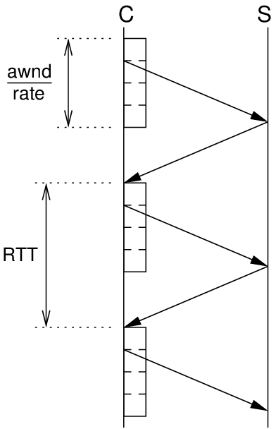
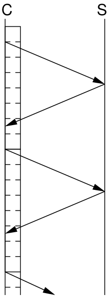
| Smaller Receive Buffer | Larger Receive Buffer |
C is the client (source/sender) and S is the server (sink/receiver). The figures show the transfer of segments from client to server, increasing in time as moving down. Assume the client knows the servers Advertised Window and it is large enough for the client to send 4 segments. The client sends these 4 segments and then must wait for an ACK to come back for each segment. When the first ACK is received the client can send another segment and so on. If the client always has data ready to send and the maximum buffer space at the server is 4 segments, then the behaviour will be: client sends 4 segments, then waits for the first ACK, then sends another 4 segments, then waits for the first ACK, and so on. The time to transmit one data segment, for that data segment to reach the server, the ACK to be transmitted back and reach the client is the round trip time (RTT). Therefore the client sends 4 segments every RTT, and the server receives 4 segments every RTT.
(The above two diagrams, with a more detailed explanation and some equations are available a 3 page PDF document for my courses. Some other figures are in my lectures from ITS323 and ITS413).
The figure on the left assumes the time to transmit 4 segments is less than the RTT. The figure on the right shows a case where the Advertised Window is double in size, 8 segments, and the time to transmit these 8 segments is greater than the RTT. The result is the ACK for the first segment in the window is received (allowing another segment to be sent) before the client has finished sending those 8 segments. The client doesn't have to spend any time waiting for an ACK - it is always transmitting segments.
In summary, if the time to transmit a window size of segments is less than the RTT, then the client spends some time waiting leading to a lower than ideal sending rate (and throughput, as assuming no packet loss, the throughput is approximately equivalent to the sending rate minus any headers). If the time to transmit the window of segments is greater than or equal to the RTT (i.e. awnd/rate >= RTT), then the client is sending all the time leading to the ideal sending rate and throughput.
And a reminder the window size depends on the buffer size at the receiver, and the time to transmit a window of segments is the size of that window divided by the path rate or bandwidth.
The question now is "What size should the buffer at the receiver be to achieve the ideal sending rate?". It should be greater than or equal to the path bandwidth multiplied by the RTT, i.e. awnd >= rate * RTT. This value is commonly referred to as the Bandwidth Delay Product (BDP): the product of the path bandwidth and the path RTT.
In summary, if the receiver buffer size is greater than or equal to the BDP then from a flow control perspective TCP will achieve the optimal throughput. If the buffer is smaller than the BDP then the throughput will be lower than optimal, specifically it will be proportional to awnd/RTT
Next we see how to set the receiver buffer size.
Setting TCP Parameters including Receiver Window Size
We can set the buffer space available at the receiver for TCP using a kernel configuration parameter:
$ sysctl net.ipv4.tcp_rmem
net.ipv4.tcp_rmem = 4096	87380	3950304
The first value, 4096 Bytes, is the minimum size that is used by each TCP socket. The middle value, 87380 Bytes, is the default value. And the third value, 3950304 Bytes, is the maximum value. So by default when an application creates a TCP socket the receive buffer is allocated 87380 Bytes. But an application can use the sockets API to change the value, so long as its between the minimum and maximum. We'll return to how this is achieved in a moment. But first, you can change the values of the receiver buffer space:
$ sudo sysctl net.ipv4.tcp_rmem="4096 100000 6000000"
net.ipv4.tcp_rmem = 4096 100000 6000000
What are the best values? Well that depends on the BDP and other factors (how many TCP connections are you going to use at the same time, how much memory is available, ...). In fact rather than you setting the value, the Linux kernel auto-tunes the default value (within the min,max range) trying to determine the best value for the given BDP of your network. So although the initial default is 87380 Bytes, it may actually be changed by the kernel. The feature that performs this auto-tuning is tcp_modderate_rcvbuf:
$ sysctl net.ipv4.tcp_moderate_rcvbuf
net.ipv4.tcp_moderate_rcvbuf = 1
If for running experiments you want to manually change the receive buffer size (either in the kernel or using your application, such as iperf) then I suggest turning off this auto-tuning capability:
$ sudo sysctl net.ipv4.tcp_moderate_rcvbuf=0
net.ipv4.tcp_moderate_rcvbuf = 0
With auto-tuning turned off, when your application starts the receive buffer size will take the default value, e.g. 87380 Bytes. But as noted above, your application can also manually set the value when it creates a socket. In C the functions getsockopt() and setsockopt() are used to get and set socket options, respectively. See the man pages for details on using these functions, e.g. man setsockopt. The set of options available is described in the socket man page (man -S7 socket). For the receive buffer size the option is SO_RCVBUF. Directly from the man page on my computer we see:
      SO_RCVBUF
              Sets or gets the maximum socket receive buffer in bytes.  The kernel doubles this value (to allow space for
              bookkeeping overhead) when it is set using setsockopt(2), and this doubled value is  returned  by  getsock‐
              opt(2).   The  default  value  is  set by the /proc/sys/net/core/rmem_default file, and the maximum allowed
              value is set by the /proc/sys/net/core/rmem_max file.  The minimum (doubled) value for this option is 256.
Take for example iperf which sets the SO_RCVBUF option when using the -w option on the server:
$ iperf -s -w 20K
------------------------------------------------------------
Server listening on TCP port 5001
TCP window size: 40.0 KByte (WARNING: requested 20.0 KByte)
------------------------------------------------------------
The application sets the receive buffer to 20KB using the -w option, but the kernel doubles the buffer size to 40KB (as reported in the output of iperf above) to make sure there is space for both the received segments AND information about the TCP connection stored by the kernel. So if the kernel allocates 40KB for the receive buffer, how much is reserved for receiving segments? Or what is the maximum Advertised Window that the receiver can send to the source? (This question applies both when the application sets the receive buffer as iperf did above and if the default value, say 87380 Bytes, is used)
From my experiments (and its probably written somewhere? - see the update below), the kernel allocates 75% of the buffer space for receiving segments. If the application uses the default 87380 Bytes, then the maximum Advertised Window is 65535 Bytes. From the perspective of TCP flow control, the maximum Advertised Window controls the sending rate. If the application manually sets the receive buffer space to 40KB (i.e. in iperf you use -w 20K), then 30KB is allocated to received segments.
Update (2012-04-24): It is probably written somewhere? Yes it is. In the tcp man page under the tcp_adv_win_scale, which has a default value of 2, it says the overhead that is not used by TCP is bytes/2^tcp_adv_win_scale, i.e. one quarter, meaning 75% is used by TCP.
Update (2013-01-16): The above update from 2012-04-24 mentions a default value of tcp_adv_win_scale of 2, meaning 75% of the allocated space is the advertised window size. However recent changes to the Linux kernel set the default to 1, meaning only 50% of the space is used as advertised window. The remainder of this document continues to refer to the old value: 2 and 75%. Be aware that if you are running experiments, your values may be different. In Ubuntu 12.04 LTS, kernel 3.2.0-35, the default of 1 is used.
Now you can set the receive buffer to a value that matches your network BDP to achieve optimal throughput. Calculate the BDP, multiple by 4/3, and set the receive buffer in the kernel (net.ipv4.tcp_rmem) or within the application (SO_RCVBUF) to the answer (or greater than the answer). Some examples are in the table below. Next we'll finally run some experiments to confirm how the BDP impacts on TCP throughput.
| Scenario | Bandwidth [Mb/s] | RTT [ms] | BDP [Bytes] | Receive Buffer [Bytes] |
|---|---|---|---|---|
| Fast Ethernet, single link | 100 | 1 | 12,500 | 16,667 |
| Fast Ethernet, LAN | 100 | 10 | 125,000 | 166,667 |
| Gigabit Ethernet, single link | 1000 | 1 | 125,000 | 166,667 |
| Home ADSL | 6 | 50 | 37,500 | 50,000 |
TCP Throughput Results using iperf
In this set of experiments I have a path bandwidth of 100Mb/s. I want to set the RTT of the path to be 10ms. Of course with my two computers connected to a switch the actual RTT is much less (about 0.5ms). To artificially set the delay I will use tc. I have another post that explains how tc works. I'll set the one way delay on both sender and receiver to be 5ms, creating a 10ms RTT. Use the following command on both computers (setting the interface eth0 to your interface identifier):
$ sudo tc qdisc add dev eth0 root netem delay 5ms
Lets test using ping (my receiver IP is 192.168.1.34):
$ ping -c 5 192.168.1.34
PING 192.168.1.34 (192.168.1.34) 56(84) bytes of data.
64 bytes from 192.168.1.34: icmp_req=1 ttl=64 time=10.5 ms
64 bytes from 192.168.1.34: icmp_req=2 ttl=64 time=10.5 ms
64 bytes from 192.168.1.34: icmp_req=3 ttl=64 time=10.5 ms
64 bytes from 192.168.1.34: icmp_req=4 ttl=64 time=10.5 ms
64 bytes from 192.168.1.34: icmp_req=5 ttl=64 time=10.5 ms

--- 192.168.1.34 ping statistics ---
5 packets transmitted, 5 received, 0% packet loss, time 4006ms
rtt min/avg/max/mdev = 10.556/10.567/10.583/0.130 ms
We see the average RTT is 10.5ms. The real 0.5ms RTT plus the extra 5ms delay added by the source and the extra 5ms delay added by the receiver.
With a 100Mb/s bandwidth and 10ms RTT the BDP is 125KB. We expect to see TCP throughput to be maximum when the Advertised Window is larger than 125KB, while the throughput should be approximately awnd/RTT when less than 125KB.
In the experiments I am going to capture the traffic so I can inspect the invidiual packets later, especially the value of the Window field in the TCP header sent by the receiver, i.e. the Advertised Window. This step is not necessary, but I will show how the capture can be used at the end. On the source:
$ sudo tcpdump -i eth0 -s 1500 -w buffer075.cap "host 192.168.1.34 and port 5001"
In the first experiment I will set the receiver buffer size to 100KB, meaning the maximum Advertised Window will be 75KB. I will use the -w in iperf (rather than setting the default kernel parameter). Recall that when an application sets the receive buffer size, the kernel doubles the value, and 75% of that double value is available for receiving segments. As an added complexity, iperf uses Kilo to mean 1024 Bytes, not the standard 1000 Bytes. So I will not use K when using the -w option and I will convert all values reported by iperf into the standard K = 1000 Bytes. So start iperf on the receiver:
$ iperf -s -w 50000
------------------------------------------------------------
Server listening on TCP port 5001
TCP window size: 97.7 KByte (WARNING: requested 48.8 KByte)
------------------------------------------------------------
I requested 50,000 Bytes (or 48.8 x 1024 Bytes) but the kernel allocated double the space, i.e. 100,000 Bytes (or 97.7 x 1024 Bytes). Of those 100,000 Bytes, 75% or 75KB, are allocated for receiving segments.
Now start the test on the sender:
$ iperf -c 192.168.1.34
------------------------------------------------------------
Client connecting to 192.168.1.34, TCP port 5001
TCP window size: 16.0 KByte (default)
------------------------------------------------------------
[  3] local 192.168.1.3 port 32986 connected with 192.168.1.34 port 5001
[ ID] Interval       Transfer     Bandwidth
[  3]  0.0-10.0 sec  64.6 MBytes  54.1 Mbits/sec
The results show a throughput (iperf calls it bandwidth) of 54.1Mb/s. Does that make sense? The maximum Advertised Window (75KB) is less than BDP (125KB), therefore we expect the throughput to be awnd/RTT, i.e. 75KB/10ms = 60Mb/s. It's close enough, considering that there are some overheads with using Ethernet and that at the start of the connection the maximum Advertised Window is not immediately used (because of congestion control).
Now run another test by restarting iperf on the server with a different value for -w. I've run several tests - the results are reported below. With a BDP of 125KB, the first 2 tests have a maximum Advertised Window less than BDP and so we expect less than optimal throughput. For the next 3 tests the maximum Advertised Window is equal to or greater than the BDP and so in theory we should obtain optimal throughput. What is optimal throughput? Well the link rate is 100Mb/s, the throughput is slightly less due to overheads, as we see about 94Mb/s.
Update (2013-01-23): Why is the throughput about 94Mb/s when the data rate is 100Mb/s? Because of the overheads of using TCP, IP and Ethernet. The steps for delivering the application data across the link are:
- The application, iperf, creates random data and delivers it to TCP. How much data comes from iperf? 1432 Bytes. You can see this from a capture in the results below.
- TCP adds a header and sends to IP. How big is the TCP header? The default size is 20 Bytes, but in this test, as can be seen in the captures, there are optional fields bringing the header size to 32 Bytes.
- IP adds a header and sends to Ethernet. The IP header is 20 Bytes, its default size.
- Ethernet in a switched LAN adds a header and trailer and transmits the frame on the link. Wikipedia has a good illustratative diagram of the Ethernet frame structure. The frame contains a preamble and frame delimiter, consisting of 8 Bytes in total. Then there is the header as seen in the capture - containing addresses and type - of 14 Bytes. Then the data: 20 Byte IP header + 32 Byte TCP header + 1432 Bytes of application data. Then a 4 Byte frame check sequence is added as the trailer. Before sending the next frame, there is a gap, equivalent to the time of transmitting 12 Bytes.
So the total size of the Ethernet frame is: 1522 Bytes. This is 90 Bytes of header and 1432 Bytes of application data. Hence the efficiency of using the link to send application data is 1432/1522 = 94.09%. With a 100Mb/s link rate, the maximum throughput expected is 94.09Mb/s.
| Bandwidth | RTT | BDP | -w | Buffer Size | Max Adv. Window | Expected Thr. | Measured Thr. | Accuracy |
|---|---|---|---|---|---|---|---|---|
| [Mb/s] | [ms] | [KBytes] | [KBytes] | [KBytes] | [KBytes] | [Mb/s] | [Mb/s] | [%] |
| 100 | 10 | 125 | 50 | 100 | 75 | 60 | 54.1 | 90 |
| 100 | 10 | 125 | 75 | 150 | 112.5 | 90 | 82.3 | 91 |
| 100 | 10 | 125 | 83 | 166 | 125 | 100 | 91.1 | 91 |
| 100 | 10 | 125 | 100 | 200 | 150 | 100 | 94.0 | 94 |
| 100 | 10 | 125 | 125 | 250 | 187.5 | 100 | 94.1 | 94 |
Although the throughput results do not exactly equal the theoretical values (and I should run multiple tests over longer times to be more accurate) the results do match the expected behaviour: when the maximum Advertised Window is greater than the BDP TCP flow control allows the source to use all the available bandwidth giving maximum throughput. When less than the BDP the throughput is limited by the size of the maximum Advertised Window (which in turn is limited by the receive buffer size).
The final step: open the packets captured by tcpdump in Wireshark and look at the Window field in the TCP segments sent by the receiver computer. Below is a screenshot of the first set of packets sent by the receiver (192.168.1.34) from my first test (maximum Advertised Window of 75KB). Alternatively you can download my captures and look at them yourself by clicking on the links in the Measured Throughput column of the above table.
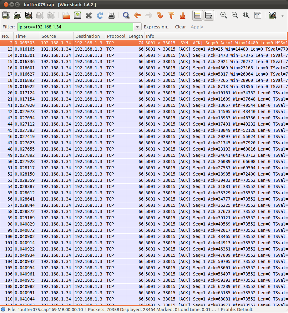
The packets shown are all ACKs sent by the TCP receiver to the source. Look at the value of the Window field in the TCP header. Initially it varies but soon it reaches 73552 Bytes. Looking through the rest of the packets it turns out this is the maximum Advertised Window sent by the TCP receiver. We expected 75000 Bytes. What's the difference? 1448 Bytes which is the length of 1 DATA segment sent by the TCP source (1500 Bytes of Ethernet data minus the 20 Byte IP header, minus the 20 Byte TCP header and the 12 Bytes of TCP header options). Most likely the receiver always has 1 DATA segment still in the buffer when it sends the ACK, so of the 75000 Bytes allocated there are only 73552 Bytes of space available for more data segments.
Conclusions
- The maximum space a receiver has available to store received packets should be larger than the Bandwidth Delay Product to achieve maximum throughput when using flow control.
- Networking is complex; much more complex than what can be covered in undergraduate data communication lectures.
- Performing experiments is a good way to understand how communication protocols work.
- When performing experiments, make sure your computers and network are setup appropriately. Turn off advanced features to run experiments (and later turn them on to see how they impact on performance).
Created on Sun, 11 Mar 2012, 5:24pm
Last changed on Wed, 23 Jan 2013, 7:16pm