Talking to Martians: Communications with Mars Curiosity Rover
On 6 August 2012 the Mars Curiosity rover completed a successful landing on Mars. On top of taking nice pictures of the Mars landscape, Curiosity has a variety of scientific goals. The mission also demonstrates technologies for overcoming the challenges for data communications in such a complex and unique environment. In the following I try to summarise some interesting parts of the project related to data communications. My intention is to keep it simple enough so that my ITS323 Introduction to Data Communications students can connect what they've learnt in class to this real, complex and exciting project.

The Mars Curiosity rover is part of a much larger project by NASA, the Mars Science Laboratory. For communications back to Earth, the rover makes use of intermediate spacecraft, Odyssey and the Mars Reconnaissance Orbiter, and a network of ground stations in the US, Spain and Australia. I will describe the overall system, and then the important components for communications: Curiosity, Odyssey, MRO, and the ground stations. Along the way I'll give several examples of communications characteristics and performance, such as path loss, delay, antenna gains and spectrum.
My main sources of information are the Mars Science Laboratory sites by NASA and JPL, the Jet Propulsion Lab managed by CalTech. Much of the technical information about the telecommunications links comes from the Design and Performance Summary series of NASA/JPL reports, in particular:
- Mars Reconnaissance Orbiter Telecommunications, by Taylor, Lee and Shambayati; September 2006.
- Mars Science Laboratory Telecommunications System Design, by Makosky, Illot and Taylor; November 2009.
- Odyssey Telecommunications, by Makovsky, Barbieri and Tung; October 2002.
Technical information about the ground stations, NASA's Deep Space Network, is from the DSN Telecommunications Link Design Handbook. Wikipedia also has lots of useful details.
System Overview
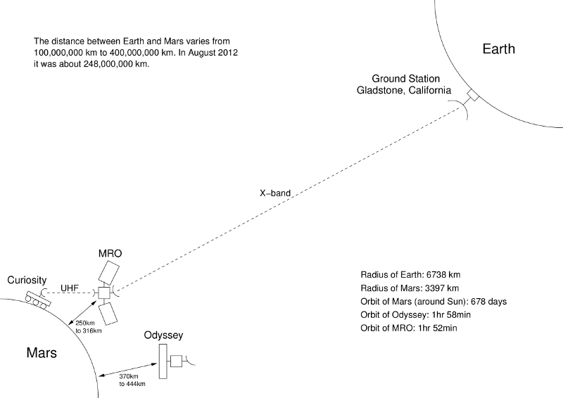
The distance between Mars and Earth changes over time, roughly from between 100,000,000 km and 400,000,000 km. In August 2012 it is about 248,000,000 km. A day on Mars (known as a sol) is about the same as an Earth day, 24 hours 39 minutes. A year on Mars is about 686 Earth days.
NASA (and in the case of Express orbiter, the European Space Agency) has launched several spacecraft and landers to study Mars. The ones currently in use are:
- Odyssey orbiter (2001)
- Express orbiter (2003)
- Opportunity lander (2004)
- Reconnaissance orbiter (2006)
- Curiosity lander (2012)
In addition, Beagle 2 was a lander carried by the Express orbiter that was lost after launched. Spirit was a lander with Opportunity which has sinced ceased communications.
Mars Curiosity lander (or rover) is the most recent addition to the Mars exploration missions, referred to by NASA as the Mars Science Laboratory.
To save on power, the Mars Curiosity rover can communicate with Earth via other spacecraft orbitting Mars, in particaulr MRO and Odyssey, rather than sending direct to Earth. There are three primary ground stations on Earth: Gladstone, California; Canberra, Australia; and Madrid, Spain. Each have similar setups, including one 70 metre diameter antenna and two or more 34 metre antennas. These are the ground stations for NASA's Deep Space Network (DSN). A diagram of the components for Curiosity communications is shown below.
The following describes the main characteristics, with focus on communication capabilities, of Odyssey, MRO, Curiosity and DSN.
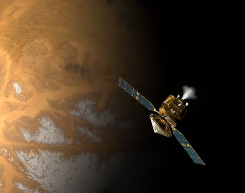
MRO
The Mars Reconnaissance Orbiter (MRO) is a 1000 kg spacecraft (which also carried about another 1000 kg of fuel) launched in 2005. It has two goals: conduct science experiments to better understand the climate and surface of Mars, especially with regard to finding water sources; act as a communications relay back to Earth for other missions that have spacecraft or rovers near or on Mars. MRO orbits around Mars every 1 hour and 52 minutes, with the closest point to the surface being 250 km and the furthest 316 km.
In terms of communications capabilities, MRO has transceivers at three different frequency bands:
- X-band: 8 GHz
- Primary communications with Earth during the launch and cruise stage and also while orbitting Mars. The centre frequencies used are 8.439 GHz for transmit (Tx) and 7.183 GHz for receive (Rx). A bandwidth of 50 MHz is allocated.
- Ka-band: 32 GHz
- Experimental payload to investigate the performance for space to Earth communications compared to using X-band. Only transmit is used by MRO. The centre frequency is 32.0 GHz. A bandwidth of 500 MHz is allocated for Ka-band.
- UHF: 400 MHz
- Used for relaying commands and data from rovers on Mars' surface back to Earth. MRO has 16 preset channels, ranging in frequency from 390 MHz up to 450 MHz. When using half-duplex (transmit or receive, not both), any channel can be chosen, but when using full-duplex Tx channels are chosen from the range 435 to 450 MHz and Rx channels from the range 390 to 405 MHz.
Naming Schemes in Electromagnetic Spectrum
The electromagnetic spectrum covers the range of frequencies of electromagentic signals. Portions of the spectrum have been given names. Unfortunately the are different naming schemes and sometimes the exact frequencies for a particular name are not clearly defined. A common naming system for regions of the spectrum include: radio, microwave, infrared, visible light, ultraviolet, X-rays and gamma rays. Some more precise schemes have been defined by ITU and IEEE. ITU defines radio bands with names based on the frequency, such as Very Low Frequency (VLF), High Frequency (HF), Ultra High Frequency (UHF) and Tremendously High Frequency (THF). As an alternative, IEEE uses the common HF, VHF and UHF, but mainly letters for other portions of the spectrum, e.g. S-band, X-band, Ku-band, Ka-band. A summary of some of the more common names is below.

MRO has four antennas:
-
High Gain Antenna (HGA), a 3 metre diameter parabolic dish antenna. It is used for X-band transmit and receive, and Ka-band transmit (MRO cannot receive Ka-band signals). The HGA is intended for primary communications to Earth when orbiting Mars. The antenna gain depends on the signal frequency and how accurately it is pointed at the ground station dish:
- X-band Tx: 46.7 dBi
- X-band Rx: 45.2 dBi
- Ka-band Tx: 56.4 dBi
Note that these gains are decreased when the antenna is pointed slightly off centre. For example, if the antenna is 10 milli radians off centre, the X-band Tx antenna gain is reduced by about 8 dB, down to 38.7 dBi.
-
Low Gain Antenna 1 (LGA1), attached to the HGA and pointing in the same direction. LGA1 and LGA2 are intended for special purpose communications to Earth, e.g. during launch and in case of emergencies. They have a much wider beamwidth than the HGA, meaning they don't have to pointed as accurately to the Earth ground station as does the HGA. The disadvantage is that they have lower gain and therefore the signals received will be much weaker, leading to lower data rates. The antenna gain is:
- X-band Tx: 8.8 dBi
- X-band Rx: 8.4 dBi
- Low Gain Antenna 2 (LGA2), also attached to the HGA but pointing in the opposite direction. Same gain characteristics as LGA1.
- UHF antenna, intended for communications with landers on Mars, e.g. Curiosity. The antenna gain varies significantly based on frequency and pointing direction. For example, at 437 MHz the gain is 5 dBi, but varies up to almost 6 dBi when 30 degrees off centre. At 401 MHz the gain is 2 dBi at centre, and up to 4 dBi 30 degrees off centre.
Antenna Gain
A key design aim for space (and in general, wireless) communication systems is ensuring that one end point (e.g. MRO) transmits a signal with stronger enough power such that it will be successfully received by the other end point (e.g. a ground station). A spacecraft should transmit with as little as power as possible, so that it doesn't consume too much of the system energy source (provided by solar cells). So what is the ideal transmit power, PTx? Well, it depends on the minimum power level that the receiver can successfully receiver (which is normally specified as part of the receiver; it depends on the antenna and electronic circuitry - some values are given shortly) and how much power is lost between transmitter and receiver.
A key characteristic of an antenna is its gain. Typically measured in dBi, the antenna gain indicates how much stronger the antenna is when compared to an ideal isotropic antenna (the i in dBi is for isotropic; decibels relative to an isotropic antenna). An isotropic antenna radiates power equally in all directions. A real antenna concentrates some of the power into a particular direction. Therefore in that particular direction, at a point say 1 metre away from the transmitter, the power measured if using a real (directional) antenna will be stronger than if using an isotropic antenna. The gain is a measure of how much stronger. (As a real antenna concentrates power into a particular direction, the power will be weaker in other directions, i.e. the gain will be less, in some cases a loss. The gain in each direction depends on the antenna design, and is often specified graphically as an antenna pattern plot.)
The gain of an antenna depends on its size, specifically its effective area, and the wavelength of the signal being transmitter/received:
G = 4 × π × Ae / λ2 The effective area of a parabolic antenna, Ae, depends on its design and build, but is always less than the physical area. Typical values range from 0.35 to 0.70 times the physical area. For the HGA on MRO lets say it 0.66, i.e.:
Ae = 0.66 × APhysical where the physical area, Aphysical, of a dish with radius r is approximately the area of a circle with radius r. For the HGA the diameter is 3 metres, i.e. a radius of 1.5 metres. So the effective area is:
Ae = 0.66 × π × 1.52
= 4.665 m2When transmitting a signal at frequency 8.439 GHz, and hence wavelength of 0.03555 m, the gain of the HGA is:
GTx = 4 × π 4.665 / 0.035552
= 46387.5That is, in one direction the HGA is 46387.5 times stronger than an isotropic antenna. This absolute antenna gain can be expressed in dBi:
GTx = 10 × log10 (46387.5)
= 46.7 dBiChecking the specifications of the MRO HGA (Table 2-2, page 18) and we indeed see this calculated antenna gain is correct. Later we'll see how they are used in calculating the path loss between MRO and Earth.
The maximum transmit power for the MRO transceivers is:
- X-band: 100 Watts
- Ka-band: 35 Watts
- UHF: 5 Watts in full-duplex, 7 Watts in half-duplex
Note the UHF transceiver can operate in half-duplex when it is either transmitting or receiving, but not both at the same time.
The transceivers have receive power thresholds, the minimum power at which a received signal can be understood. The transceiver for the X-band and Ka-band signals (used with HGA, LGA1 and LGA2) has a receive power threshold of -156 dBm. The UHF transceiver has a receiver power threshold of -130.8 dBm. Note that the thresholds differ depending on the data rate, e.g. when using low data rates, the transceiver can understand lower powered receive signals; when using higher data rates the transceiver needs to receive stronger signals. For example, the the UHF transceiver the receive threshold for the lowest data rate, 1kb/s, is -130.8 dBm. But for 2Mb/s, the threshold is -99.6 dBm.
Receive Power Threshold and dBm
The receive power threshold is a measure of the sensitivity of the receiver. A receiver with a high sensitivity means it can successfully receive and decode low powered signals, that is, its receive power power threshold is low. With a low sensitivity, the receiver must receive higher power signals in order for it to successfully decode and "understand" the data.
The receive power threshold of a receiver is part of the devices specification (for example, if you can find the detailed specs of wireless LAN devices, often you'll find the receiver power threshold, also called receive sensitivity). The value depends on different factors, including the circuit design and coding scheme used. As a result, the receive power threshold varies for different data rates: the higher the data rate, the higher the threshold. A practical consequence of this is seen in the distance at which a particular data rate can be used: the further the transmitter is from the receiver, the weaker the signal received, and the lower data rate than can be used (again, this is demonstrated commonly in wireless LANs: as your laptop signal to/from the access point gets weaker as you move further away, the wireless LAN card will reduce the link data rate, from say 54 Mb/s down to 48 Mb/s and eventually down to 1 Mb/s.)
The receive power threshold is usually measured in dBm, decibels relative to 1 mW (more precisely it should be dBmW, but it is normally abbreviated to dBm). Conversion between mW and dBm is as follows:
PdBm = 10 × log10 (PmW) For example, 100mW is equivalent to 20dBm, and -100 dBm is equivalent to 0.1 picoWatts (10-10 mW).
The data rate that MRO can send data back to Earth depends on the received signal strength: the weaker the signal received at Earth the lower the data rate used. The primary contributor to change of the signal strength is distance. As stated previously, the distance between Mars and Earth varies from about 100 million to 400 million km. MRO is designed to send at a minimum data rate of 500 kb/s when the signal is weakest (the distance is largest), and 6 Mb/s when the signal is strongest.
As the NASA Deep Space Network (described shortly) is used for multiple missions, there is limited times for communications between MRO and Earth. During the primary science mission of MRO, it was allocated:
- Two passes a day from X-band transceiver to the DSN 34 metre dish. About 8 hours a day the MRO is behind Mars (no line-of-sight to Earth), leaving 16 hours a day of potential communications time. During the primary science mission of MRO it was scheduled to transmit data about 10 or 11 hours per day.
- Three passes a week from X-band to the DSN 70 metre dish
- Two passes a week for Ka-band to the DSN 34 metre dish
MRO is the primary relay node for Curiosity to communicate to Earth (Orbiter is the backup relay). Communications is using a store-and-forward mode. For data from Mars back to Earth, Curiosity uses the UHF band to transmit to MRO while within range. Curiosity has about a 6 to 9 minute window for communications about 2 times per day. The data received by MRO is stored in the on-board memory. MRO has allocated 5 Gb per day for storage for all landers. When MRO can establish an X-band link, the data is relayed back to Earth. A similar approach is used for the forward direction, Earth to Curiosity, i.e. sending command and control messages. For this, MRO has allocated 30 Mb per day for storage.
For reliability, the link between Curiosity and MRO uses a protocol called Proximity-1, defined by CCDCS. No such protocol is available on the X-band link from MRO to Earth. In this case a simple error control protocol is used: the MRO sends each frame twice to Earth. I haven't studied how Proximity-1 works yet; if I get a chance I'll describe it in another article.
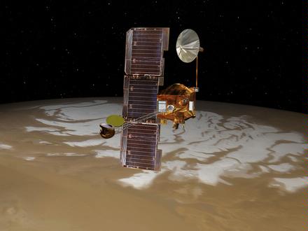
Odyssey
The Mars Odyssey Orbiter is a 380 kg spacecraft (plus 350 kg of fuel) launched in 2001. Odyssey includes several science payloads, in particular spectrometers to take pictures (including infrared) of Mars' surface, to measure radiation levels and to measure neutrons in order to look for water and ice in the soil. Odyssey can also act as a relay for landers, as a backup to MRO. Odyssey orbits around Mars every 1 hour and 58 minutes, with the closest point to the surface being 370 km and the furthest 444 km.
The following summarizes some of the communication characteristics of Odyssey.
Odyssey has three X-band antennas and one UHF antenna:
- High Gain Antenna (HGA), used for primary Earth communications, both transmit and receive. Parabolic antenna with 1.3 m diameter. Transmit frequency is 8406 MHz and gain is 38.3 dBi. Receive frequency is 7155 MHz and gain is 36.6 dBi. A beamwidth of around 2 degrees.
- Medium Gain Antenna (MGA), a transmit only horn antenna, pointing in same direction as HGA. Transmit frequency is 8406 MHz and gain is 16.5 dBi. A beamwidth of 28 degrees.
- Low Gain Antenna (LGA), a receive only patch antenna used for emergency communications. Receive frequency is 7155 MHz and gain is 7 dBi. A beamwidth of 82 degrees.
- UHF antenna, for communications to landers. Peak antenna gain of 5 dBi, using frequencies 401 MHz and 437 MHz. A beamwidth of 80 degrees.
The X-band transceiver has a maximum transmit power of 15 W, transmit frequency of 8406 MHz and receive frequency of 7155 MHz. It is designed to support a minimum data rate of 3.6 kb/s downlink to Earth and 125 b/s for uplink commands.
The UHF transceiver has a maximum transmit power of 12 W, forward frequency of 437 MHz, return frequency of 401 MHz and data rates of 8, 32, 128 and 256 kb/s.
Further details about Odyssey can be found in the Odyssey Telecommunications report. Included are some good examples of the telecommunication performance (e.g. table 5-3 on page 42, table 5-5 on page 49) showing the design parameters for the link budget (e.g. transmit power, path loss, receive power, signal to noise ratio), as well as their average real measured values.
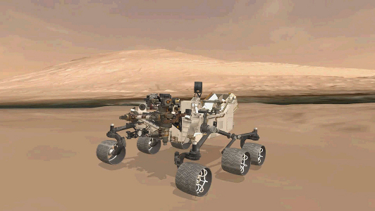
Curiosity
The spacecraft carrying Curiosity rover was launched on 26 November 2011. It spent a bit under a year cruising to Mars and approaching a point where it could descend on to the surface of Mars. It successfully landed on 6 August 2012. The intended lifetime of Curiosity on Mars is one Martian year (686 Earth days).
Curiosity has three antennas:
- High Gain Antenna (HGA). A 25×29cm patch antenna with transmit gain of 25.5 dBi and receive gain of 20.2 dBi. Used for direct-to-Earth (DTE) communcations for telemetry and direct-from-Earth (DFE) for commanding.
- Low Gain Antenna (LGA). Gain of 5dBi. Used for low rate DFE commands. Not intended for use for DTE as the data rate is very low.
- UHF antenna. Used for communicating to/from Earth via the Mars relays: MRO and as a backup, Odyssey.
The HGA and LGA are used for X-band communications. The DTE transmit power is 15 W. The minimum requirement for downlink data rate using the HGA is 160 b/s to a 34-m antenna and 800 b/s to a 70-m antenna. The uplink data rate requirement is 1 kb/s using the HGA, allowing for commands to be sent to Curiosity. As a backup the LGA can be used (it has a much wider beamwidth and therefore doesn't need as accurate positioning as the HGA), but because of the weaker signal a data rate of about 15 b/s is expected.
The downlink (relay to Curiosity) data rates range from 2 kb/s to 2048 kb/s. Odyssey only supports up to 256 kb/s. The uplink data rates range from 2kb/s to 256 kb/s (Odyssey: 8 and 32 kb/s only).
Curiosity has a number of scientific instruments on board for experiments. These include several cameras. Selected data from the instruments is to be sent back to Earth for processing. Some example images can be sorted by camera and downloaded.
As an example, consider the MastCam colour cameras. There are two MastCam cameras, taking slightly different pictures to get a 3D view. Each camera captures 1200x1200 pixels. After sending back smaller thumbnail images to Earth, specific images can be selected and transferred in RAW format (or JPEG or with a lossless compression). Each camera has a 8 Gigabyte buffer, which can stored 5,500 RAW images, meaning about 1.45MB per RAW image. Here I'm not sure on the details, but that suggests 8-bit data for each pixel, i.e. 1200 × 1200 × 8 = 11,520,000 bits = 1,440,000 Bytes.
Ground Stations
NASA operates a set of ground stations on Earth referred to as a the Deep Space Network (DSN). There are three primary sites - Goldstone, California; Canberra, Australia; and Madrid, Spain - located so the are about 120 degrees from each other, providing connectivity when spacecraft are at any position above the Earth. Each site has an almost identical set of antennas and equipment, consisting of:
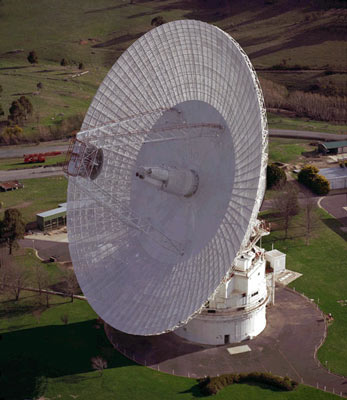
- 70 metre diameter parabolic dish antenna
- 34 metre diameter HEF parabolic dish antenna
- 34 metre diameter BWG parabolic dish antenna
The 34-m BWG is newer and has improved technologies compared to the 34-m HEF antenna. However from our "top-level" description I will consider them the same.
Technical specifications of the antennas are available from DSN Telecommunications Link Design Handbook, specifically on the 70-m, 34-m HEF and 34-m BWG. Important characteristics of the 70-m and 34-m antennas used in S-band, X-band and Ka-band are summarized in the following table (some of the antennas also support other bands, e.g. L-band and K-band).
| Antenna: | 70-m | 34-m HEF | 34-m BWG | ||||
| Band: | S | X | S | X | S | X | Ka |
| Tx Freq. Range [MHz] | 2090-2118 | 7145-7190 | 2025-2110 | 7145-7190 | 2025-2120 | 7145-7235 | 34315-34415 |
| Tx Gain [dBi] | 62.95 | 73.23 | 55.40 | 67.05 | 56.25 | 67.09 | 79.52 |
| Tx Beamwidth [degrees] | 0.128 | 0.038 | 0.258 | 0.077 | 0.263 | 0.077 | 0.016 |
| Tx Power [dBm] | 73 | 73 | 54 | 73 | 73 | 73 | 59 |
| Rx Freq. Range [MHz] | 2200-2300 | 8200-8600 | 2200-2300 | 8200-8600 | 2200-2300 | 8400-8500 | 31800-32300 |
| Rx Gain [dBi] | 63.59 | 74.55 | 56.07 | 68.41 | 56.84 | 68.24 | 79.00 |
| Rx Beamwidth [degrees] | 0.118 | 0.032 | 0.242 | 0.066 | 0.242 | 0.066 | 0.017 |
The transmit and receive frequency ranges indicate the set of frequencies at which the antenna can potentially transmit or receive. The antenna gains are given for one typical frequency in this set - it differs slightly for different frequencies. Different maximum transmit powers are supported at the sites: 20 kW (73 dBm), 800 W (59 dBm) and 250 W (54 dBm). The beamwidth is a measure of the directionality of the antenna. The direction the antenna is pointing gives full power (i.e. maximum gain). Off centre the power is reduced. The beamwidth specifies how far off centre the signal is within half of the full power. For example, a beamwidth of 0.128 degrees means 0.064 degrees in either side off centre, the power is half of the full power.
So know we have covered the space components - Curiosity on Mars, and MRO and Odyssey orbiting Mars as relays - as well as the Earth ground stations. I'll finish with two example calculations relevant to communications performance: first the path loss incurred between Earth and Mars, which brings together many of the technical specifications mentioned in the above sections, and then the delay in communicating between Earth and Mars.
Path Loss
When a communications signal is transmitted at some power level, that signal gets weaker as it propagates to a receiver. Knowing by how much the signal weakens is important for predicting the distance at which the transmitter and receiver can be separated such that they can still successfully communicate. As we've seen above, transmitters generate a signal with some power level. For example, a 34-m ground station in the DSN can use a transmit power of 20 kW (equivalent to 73 dBm). And receivers have a minimum power level at which a received signal can be successfully decoded and understood. For example, the X-band transceiver on MRO has a receive power threshold of -156 dBm (about 2.512 × 10⁻¹⁶ mW). If we know the relationship between the amount of power lost versus the distance a signal propagates, then we can predict how far away MRO can be from Earth such that the received signal power is greater than the receive power threshold. In general, with a transmit power Pt and loss factor L, the receive power, Pr will be:
Pr = Pt / L In practice, the amount of power lost depends on the distance, the signal frequency and various physical effects, e.g. diffraction, reflection and absorption. To help in designing communication links there are various mathematical models that attempt to capture the impact of these effects on power loss. An important model is that of free space path loss (others models are listed here). Under the assumption that a signal is being sent in an environment with no obstacles, e.g. a vacuum, and isotropic antennas are used at the transmitter and receiver, the path loss factor, L is calculated as:
L = ( 4 × π × d / λ )2 where d is the distance and λ is the signal wavelength (recall λ = c/f, where f is frequency and c is the speed of light). Therefore when using isotropic antennas:
Pr = Pt × λ2 / ( 4 × π × d )2 When using real, non-isotropic antennas, the received power is increased, as the transmit and receive antennas introduce some gain, Gt and Gr, compared to isotropic antennas. Including the antenna gains leads to the Friis transmission equation:
Pr = Pt × Gt × Gr × λ2 / ( 4 × π × d )2 As an example, consider the 34-m ground station on Earth transmitting an X-band signal to MRO. The signal frequency is 7.183 GHz (giving a wavelength of 0.041766 m) and the distance is 250,000,000 km. The free space path loss is:
L = ( 4 × π × 250 × 109 / 0.041766)2
= 5.66 × 1027The signal arriving at the receive antenna will be 5.66 × 1027 weaker than the signal coming out of the transmit antenna. Now taking into account the antenna gains, Gt = 67.09 dBi and Gr = 45.2 dBi (note these need to be convered into their absolute values), the receive power when using the 20 kW transmitter will be:
Pr = 20,000 × 106.709 × 104.52 / 5.66 × 1027
= 5.987 × 10⁻¹³ W = -92.2 dBmThe receive power is greater than the receive power threshold of the MRO receiver, and therefore MRO can successfully receive the signal. (In this calculation the received power is signifcantly lower than the threshold, which is good. But the threshold of -156 dBm is an absolute minimum; for reasonable data rates the threshold is most likely much higher, say between -140 dBm and -100 dBm, similar to the UHF transceiver).
The above example has considered only path loss in free space between the two antennas. In practice there are other factors that will cause signal power loss, e.g. atmospheric effects and imperfect circuitry and cabling in the transmitter and receiver. Engineers planning the transceivers and antennas to place on spacecraft need to take these other factors into account. Based on other models as well as measurements, they often create a link budget, starting with the transmit power and adding/subtracting the gains/losses of different components, leaving the receive power. An example link budgets for Odyssey communications can be found in Table 5-5 on page 59 of Odyssey Telecommunications.
Now lets consider an example that illustrates how long it takes to send data between Earth and Mars.
Propagation and Transmission Delay
How long does it take to transmit data between Curiosity and Earth? Lets consider an example when Curiosity wants to send science data (e.g. images) back to Earth via MRO. The main factors that impact on delay are:
- Transmission delay: the time to transmit the data across each of the links, depending on the amount of data to send and the data rate.
- Propagation delay: the time for the signal to propagate from transmitter to receiver, depending on the distance and propagation speed (assume the speed of light).
- Processing delay: the time the nodes (Curiosity, MRO, ground station) spend processing data upon reception/transmission.
- Queuing delay: the time data may have to wait in one node, in particular MRO. For example, Curiosity transmits to MRO, but MRO may not yet have a link to Earth, so the data must be stored at MRO and transmitted at a later stage.
The processing delay is expected to be vary small compared to the other factors, and so for now lets assume it is 0 seconds in all nodes.
The queuing delay may be significant, depending on where Curiosity is and the orbit of MRO. For now, lets assume the best case: MRO has a link to both Curiosity and DSN on Earth at the same time. Curiosity sends data, e.g. an image, to MRO, and then once fully received, MRO transmits to Earth.
Lets assume Curiosity has a 1,440,000 Byte image to send to Earth. Now lets focus on the first link, from Curiosity to MRO using UHF. Curiosity can transmit at a maximum data rate of 256 kb/s. For simplicty, lets assume there are no overheads (in practice there are, i.e. headers and control packets of Proximity-1 for error control). The transmission delay for the link is:
transCur-MRO = 1,440,000 Bytes / 256 kb/s
= 45 sThe propagation delay across this link depends on where MRO is in its orbit of Mars. Lets assume the closest point of 250 km above Curiosity. Therefore the propagation delay for the link is:
propCur-MRO = 250 km / 300,000,000 m/s
= 0.000833 sSo it takes 45.000833 s for the image to be sent from Curiosity to MRO. Now consider MRO then sending the image back to Earth.
Using X-band downlink, MRO can transmit at a maximum data rate of 6 Mb/s when it is closest to Earth (100,000,000 km - in fact in August 2012, it is much further away, about 250,000,000 km). Again, lets assume no overhead. The transmission delay for the link is:
transMRO-Earth = 1,440,000 Bytes / 6 Mb/s
= 1.92 sAnd a propagation delay of:
propMRO-Earth = 100,000,000 km / 300,000,000 m/s
= 333.333 secondsA total delay of:
total = transCur-MRO + propCur-MRO + transMRO-Earth + propMRO-Earth
= 380 sWith this simple analysis we see that the propagation delay between MRO (and generally, Mars) and Earth is by far the largest contributor to the total delay. It takes more than 5 minutes to propagate back to Earth, while the transmission delays are tens of seconds or less. In more realistic conditions, the data rate from MRO to Earth will be smaller (due to overheads, and for the MRO-Earth segment, the signal will be much weaker due to increased distance) and the distance from MRO to Earth is about 250,000,000 km. Even with smaller data rates, the propagation delay is still the largest contributor - 833 seconds or a bit less than 14 minutes. Of course it is twice as bad if the engineers want some sort of interaction with Curiosity, e.g. issue some commands to update software or perform an operation. The response time is 28 minutes!
Lets hope Curiosity and future missions continue to be successful. Although overcoming the very high delay and path loss is not possible, the experiments with Ka-band communications may lead to higher data rates so more scientific data on Mars can be collected and downloaded to Earth.
Created on Wed, 29 Aug 2012, 9:37pm
Last changed on Wed, 29 Aug 2012, 9:41pm